
A device for generating cylindrical vector polarized light beams by a polarizing prism

A technology of polarizing prisms and cylindrical vectors, applied in the field of optics, can solve the problems of low polarization of vector beams, difficulty in obtaining diffractive optical elements, and limitations in practical applications, etc.

Inactive Publication Date: 2015-09-16
UNIV OF SHANGHAI FOR SCI & TECH
View PDF7 Cites 0 Cited by
  • Summary
  • Abstract
  • Description
  • Claims
  • Application Information

AI Technical Summary

Problems solved by technology

In the previous technology, the cylindrical vector beam was generated by adding mode extraction elements in the laser resonator, which not only required a special level of technology, but also was not conducive to the transformation of real commercial lasers. large-scale use
On optics letters, researchers use polarizing films to convert circularly polarized light into cylindrical vector beams [see the literature "Production of radially and azimuthally polarized polychromatic beams," Opt. Lett.31(23), 3405-3407(2006).] , but there are several deficiencies in this method: (1) Use a polarizing film to convert radially propagating circularly polarized light into radially propagating linearly polarized light, so that the quality of the beam depends on the quality of the polarizing film, and if you want to It is difficult to obtain a high-purity cylindrical vector beam; (2) because the polarizing film is difficult to fix, it is not conducive to processing the whole device into a whole, and the mechanical stability of the polarizing film is not good, which further limits the practical application of this method
There is also a cylindrical vector beam generation method published abroad, see US Patent US7599069B2, patent name: Vector beam generator using a passively phase stable optical interferometer, this method has a complex structure, uses the principle of optical coherence to lead to high requirements for system positioning, and requires diffractive optical elements Not easy to obtain, low degree of polarization of vector beams, etc.

Method used


Image

  • A device for generating cylindrical vector polarized light beams by a polarizing prism
  • A device for generating cylindrical vector polarized light beams by a polarizing prism
  • A device for generating cylindrical vector polarized light beams by a polarizing prism

Examples


Embodiment 1

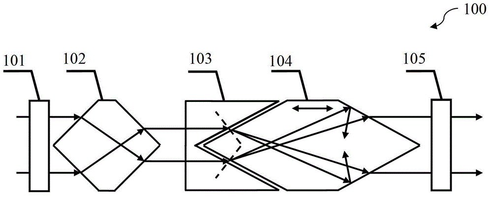
[0027] figure 1 A schematic diagram of a device for generating cylindrical vector polarized light beams for the polarizing prism involved in the present invention.

[0028] The incident light beam sequentially passes through the adjustable beam expander 101 , the common-bottom double-circle mirror transmission mirror 102 , the concave-cone transmission mirror 103 , the birefringent crystal common-bottom double cone 104 and the vortex phase plate 105 . The process of the incident beam passing through the above optical components has the following steps:

[0029] Step S1-01:

[0030]After the incident beam is reshaped by the adjustable beam expander 101, a parallel beam is generated and incident on the common-bottom biconical transmission mirror 102, and the line connecting the two cone vertices of the common-bottom biconical transmission mirror 102 coincides with the symmetry axis of the adjustable beam expander 101 , is the symmetry axis of the system, and the apex of the co...

Embodiment 2

[0051] figure 2 A schematic diagram of generating a rotationally symmetric cylindrical vector beam for the device for generating a cylindrical vector polarized beam by a polarizing prism involved in the present invention.

[0052] Such as figure 2 As shown, another embodiment of the method of the present invention is provided. Based on the above-mentioned cylindrical vector beam generation method, an incident half-wave plate 106 and an outgoing half-wave plate 106 are sequentially arranged on the outgoing beam of the vortex-type phase plate 105. A wave plate 107.

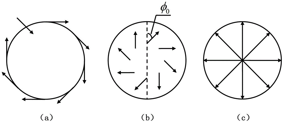
[0053] image 3 Schematic diagram of adjusting the included angle between half of the incident wave plate and half of the outgoing wave plate at the back end of the device for adjusting the polarizing prism to generate cylindrical vector polarized beams to generate rotationally symmetrical cylindrical vector beams.

[0054] Such as image 3 As shown, because the birefringent crystal common-bottom bicone 104 ma...


PUM


Abstract

The present invention provides a device for generating a cylindrical vector polarized light beam based on polarizing prisms. The device for generating the cylindrical vector polarized light beam based on the polarizing prisms is characterized by comprising an adjustable beam expanding lens, common base biconical transmitting mirrors, a concave conical transmitting mirror, double refraction crystal common base double cones, and a vortex type phase plate, wherein an incident light beam is shaped by the adjustable beam expanding lens and then is emitted out by the common base biconical transmitting mirrors to generate a hollow annular light beam; the hollow annular light beam is radiated from the air to the concave conical transmitting mirror and then is separated into the ordinary light and the extraordinary light in the double refraction crystal common base double cones; the vortex type phase plate is an optical component for modulating the phase of the light beam; the hollow annular light beam passes the concave conical transmitting mirror and carries out double refraction in the double refraction crystal common base double cones, so that the hollow annular light beam is emitted out from the double refraction crystal common base double cones to generate a circular ring-shaped cylindrical column vector beam with a vortex phase, and then the circular ring-shaped cylindrical column vector beam passes the vortex type phase plate to generate a cylindrical vector light beam. The device for generating the cylindrical vector polarized light beam based on the polarizing prisms has the characteristics of simple and stable structure, high extinction ratio and easy processing, and the generated cylindrical vector light beam possesses a high degree of polarization.

Description

technical field [0001] The invention belongs to the field of optical technology, and relates to a cylindrical vector polarized light beam generating device, in particular to a polarizing prism generating cylindrical vector polarized light beam device. It is mainly used in optical microscopy, laser micromachining, optical micromanipulation, optical information storage, lithography and other fields. Background technique [0002] Cylindrical vector beams have been applied to optical information storage, optical microscopic imaging, lithography, laser processing, particle control, lithography and other fields due to their special focusing properties and propagation characteristics of high numerical aperture objective lenses. . For example, after the phase and amplitude modulation of the wavefront, the cylindrical vector beam is focused by a high numerical aperture objective lens, and multi-focal points along the optical axis that can be used for particle transmission are genera...

Claims


Application Information

Patent Timeline
Patent Type & Authority Patents(China)
IPC IPC(8): G02B27/28G02B5/04
Inventor 郭汉明翁晓羽王小亚谭志华庄松林
Owner UNIV OF SHANGHAI FOR SCI & TECH
Learn More