Transparent touch panel

A touch panel, transparent technology, applied in the input/output process of instruments, electrical digital data processing, data processing, etc., can solve the problem of affecting the performance of conductive films, poor adhesion of conductive layers, and unstable adhesion of metal grids And other issues

Active Publication Date: 2013-12-04
ANHUI JINGZHUO OPTICAL DISPLAY TECH CO LTD
View PDF5 Cites 2 Cited by
  • Summary
  • Abstract
  • Description
  • Claims
  • Application Information

AI Technical Summary

Problems solved by technology

Most of the general metal grid lines are linear, which leads to the insufficient stability of the adhesion of the metal

Method used


Image

  • Transparent touch panel
  • Transparent touch panel
  • Transparent touch panel

Examples


Embodiment 1

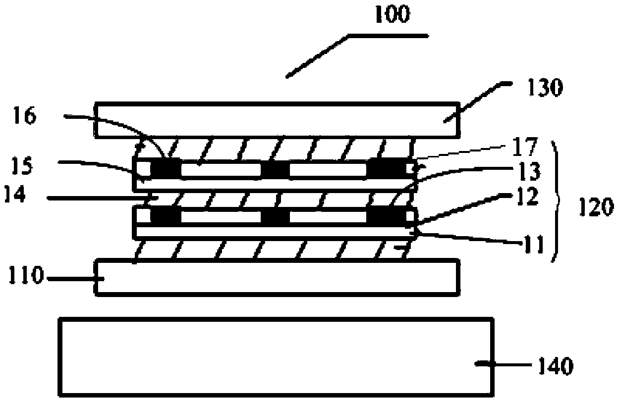
[0052] Such as figure 1 A cross-sectional view of the transparent touch panel 100 shown, the transparent touch panel 100 includes a first transparent cover layer 110 , a sensing layer 120 and a second transparent cover layer 130 from top to bottom.

[0053] The first transparent cover layer 110 is used to connect the display 140 .

[0054] The sensing layer 120 is bonded on the first transparent covering layer 110 by an adhesive. The sensing layer 120 includes a first substrate 11 , a first embossed adhesive layer 12 , a first conductive layer 13 , an adhesion-promoting layer 14 , a second substrate 15 , a second embossed adhesive layer 16 and a second conductive layer 17 connected in sequence.

[0055] The first base 11 is made of PET material, the thickness of the base 11 is 188 μm, and it is transparent.

[0056] The first embossed adhesive layer 12 is disposed on the first substrate 11 . The first embossed adhesive layer 12 is made of UV embossed adhesive material, and ...

Embodiment 2

[0071] Such as Figure 4 Shown is a cross-sectional view of the transparent touch panel 200 of this embodiment. The transparent touch panel 200 includes a first transparent cover layer 210 , a sensing layer 220 and a second transparent cover layer 230 from bottom to top.

[0072] The first transparent covering layer 210 is used for connecting the display 240 .

[0073] The sensing layer 220 is glued on the first transparent covering layer 210 . The sensing layer 220 includes a first conductive layer 43 , a first embossed adhesive layer 42 , a base layer 41 , a second embossed adhesive layer 44 and a second conductive layer 45 which are sequentially connected.

[0074] The base layer 41 is arranged in the middle of the two conductive layers. The material of the base 41 is PET, and the thickness of the base 41 is 188 μm.

[0075] The first embossed rubber layer 42 is disposed on the lower surface of the base 41 , and the first network-shaped groove is formed by embossing the ...

Embodiment 3

[0084] Such as Figure 6 Shown is a schematic cross-sectional view of the transparent touch panel 300 of this embodiment, which includes a first transparent covering layer 310 , a sensing layer 320 and a second transparent covering layer 330 from bottom to top.

[0085] The first transparent cover layer 310 is used to connect with the display 340 .

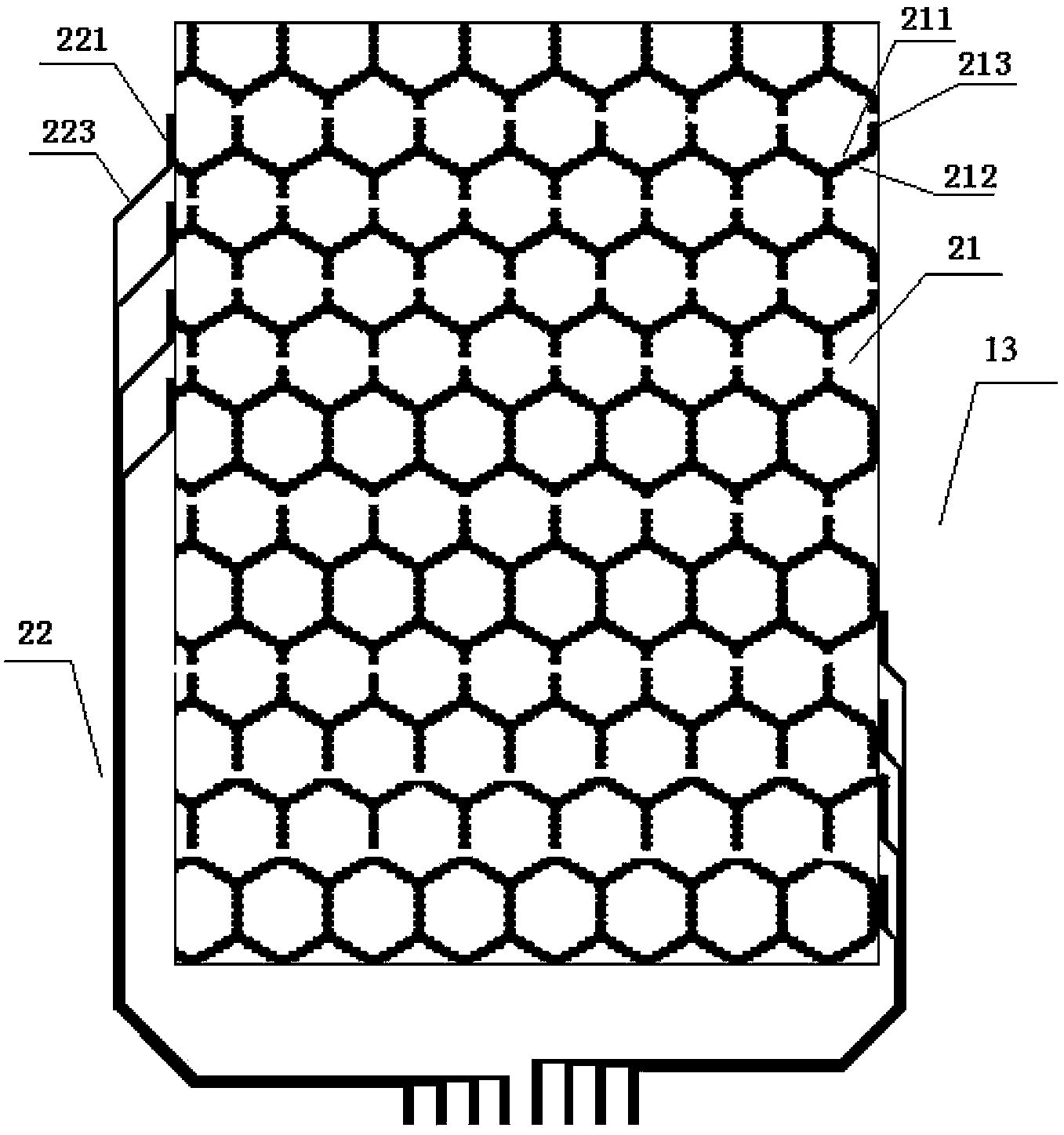
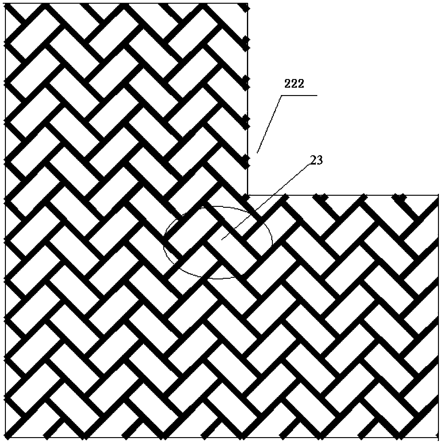
[0086] The sensing layer 320 is connected with the first transparent covering layer 310 and the second transparent covering layer 330 through an adhesive. The sensing layer 320 includes a substrate 71 , a first conductive layer 72 , an isolation layer 73 and a second conductive layer 74 connected in sequence.

[0087] The material of the base 71 is PET, and the thickness of the base 71 is 188 μm, which is transparent. On the substrate 71 , a first network linear groove is formed by embossing, the depth of the groove is 3 μm, and the width is 2.2 μm. The first grid formed by the first network linear groove is a regular grid.

...


PUM


Abstract

A transparent touch panel comprises a first transparent covering layer, an induction layer and a second transparent covering layer which are sequentially connected. The induction layer comprises a first substrate, a first imprinting adhesive layer, a first conducting layer, a tackifying layer, a second substrate, a second imprinting adhesive layer and a second conducting layer which are sequentially connected; the first imprinting adhesive layer is provided with a first network-cable-shaped groove to form into first grids; the first conducting layer comprises conducting materials which are arranged inside the groove and a first lead electrode which is connected with the conducting materials; the second imprinting adhesive layer is provided with a second network-cable-shaped groove to form into second grids; first grids are regular grids and second grids are random grids; the first network-cable-shaped groove and the edge line of the first network-cable-shaped groove are curved lines or fold lines which enables the contact areas between the conducting materials and the groove edges to be enlarged; the second conducting layer comprises the conducting materials which are arranged inside the groove and a second lead electrode which is connected with the conducting materials. The transparent touch panel can maintain good performance due to the fact that the friction force is increased due to the contact area between the conducting materials and the groove is enlarged.

Description

technical field [0001] The invention relates to a touch panel, in particular to a transparent touch panel. Background technique [0002] Transparent touch panels have a wide range of applications, and can be integrated with technologies such as multi-touch and smart display. They can be used as display terminals in various fields such as department store inquiries and vending machines, and have synergistic effects such as display, interaction, and advertising. It is expected that in the near future, with the mass production and large-scale application of this product in China, the scenes in the movie will be seen everywhere in real life, and the transparent touch panel will provide people with information services anytime and anywhere. Capacitive transparent touch panels in the prior art are classified into two types: single-point capacitive and multi-point capacitive transparent touch panels. The multi-point capacitive transparent touch panel includes a substrate, multiple...

Claims


Application Information

Patent Timeline
IPC IPC(8): G06F3/041
Inventor 杨广舟周菲曹淼倩高育龙
Owner ANHUI JINGZHUO OPTICAL DISPLAY TECH CO LTD
Why Eureka
Try Eureka