Relay pushing mechanism

A technology of pushing mechanism and relay, applied in relays, electromagnetic relays, detailed information of electromagnetic relays, etc., can solve the problems of weakening the driving force and holding force of the moving iron core, difficult to guarantee the size, and difficult to process, so as to reduce the processing cost and Material cost, improved driving force and holding force, effect of simplified machining process

Active Publication Date: 2013-12-04
XIAMEN HONGFA ELECTRIC POWER CONTROLS
View PDF3 Cites 13 Cited by
  • Summary
  • Abstract
  • Description
  • Claims
  • Application Information

AI Technical Summary

Problems solved by technology

[0004] 1. There is a counterbore between the moving iron core and the static iron core, and the return force spring 106 is placed in the counterbore of the moving iron core and the static iron core. This structure will cause the magnetic pole surface opposite the moving iron core and the static iron core to decrease. Weaken the driving force and holding force of the moving iron core. In order to ensure the driving force and holding force of the moving iron core, it is often necessary to make a larger coil, resulting in an increase in cost and an increase in product volume; at the same time, due to the compression spring 103 and return force spring 106 are distributed up and down, it is difficult to effectively ensure the synchronization of the left and right sides of the moving spring part 102, and the product performance is poor;
[0005] 2. The push rod part 102 is mainly composed of a push rod 1021 and an insulating sleeve 1022 (two upper and lower); in order to limit the insulating sleeve, it is necessary to mount a small groove 1023 or a shoulder 1024 on the push rod 1021 (such as figure 2 shown), figure 2 It is a structural schematic diagram of the push rod of the push mechanism of the relay in the prior art, which is restrained up and down by the open retaining ring and the washer; with this structure, the push rod has a complex structure, difficult processing and difficult to guarantee the size, and the assembly process is cumbersome;
[0006] 3. The common scheme of the moving spring part 101 is a straight copper sheet, or the way of riveting or welding two contacts on the straight copper sheet, one side of the straight copper sheet acts on the compression spring 103; this structure, the compression spring 103 and the copper sheet The active area of ​​the moving spring part 101 is large, especially when the contacts are ablated and worn, it is difficult to ensure the synchronization and balance of the left and right sides, and the product performance is difficult to guarantee in the later stage;
[0007] 4. The other end of the push rod 1021 is connected to the moving iron core 105 by threads first, and then the end is fixed to the moving iron core by laser welding or argon arc welding. This connection mode results in slow production efficiency and low cost high

Method used


Image

  • Relay pushing mechanism
  • Relay pushing mechanism
  • Relay pushing mechanism

Examples


Embodiment Construction

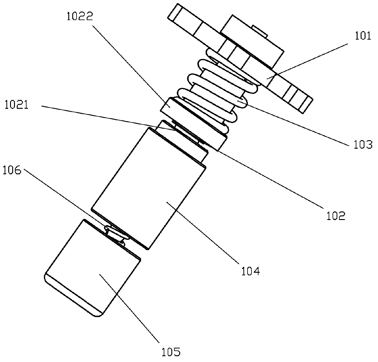
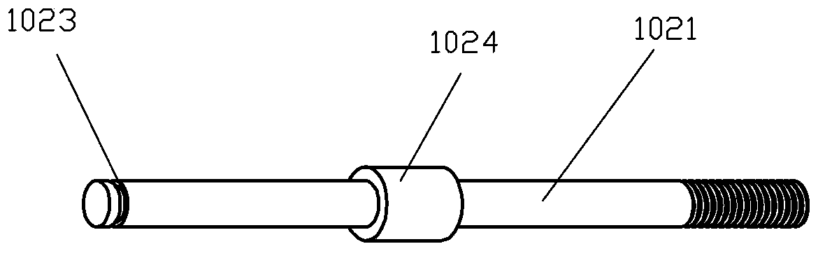
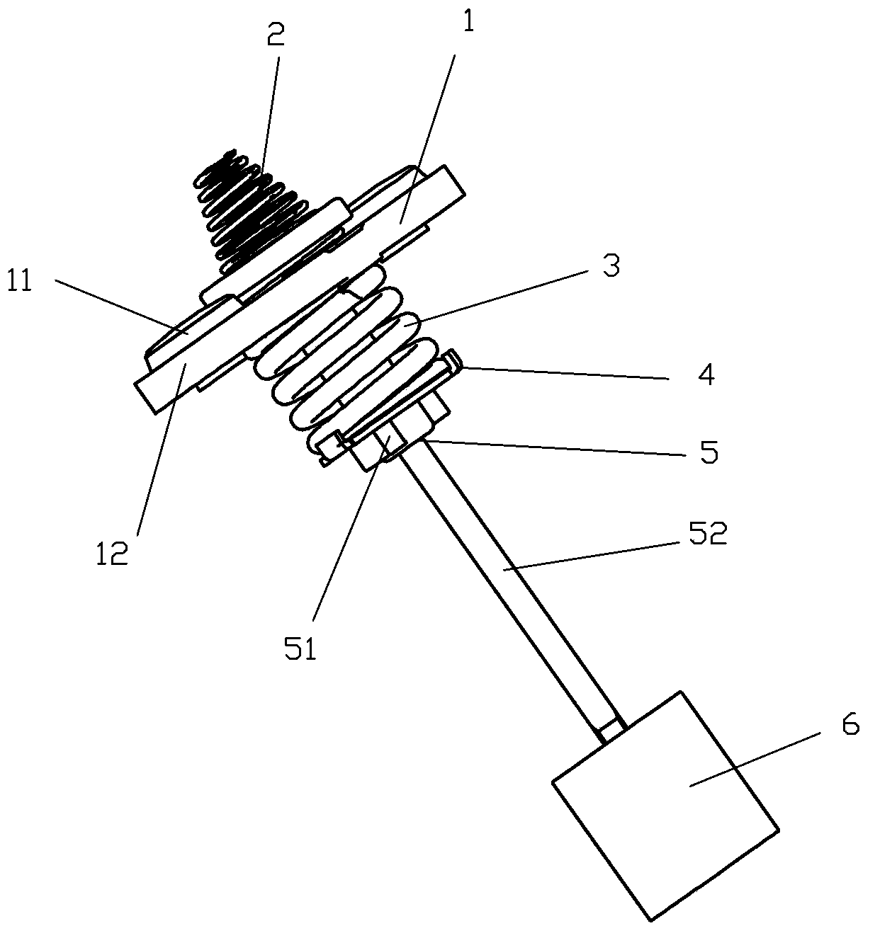
[0041] Examples, see Figure 3 to Figure 13As shown, a pushing mechanism of a relay of the present invention includes a moving spring part 1, a return spring 2, a main spring 3, a fixed plate 4, a pushing rod part 5 and a moving iron core 6; the pushing rod part 5 includes an insulating sleeve 51 and push rod 52; the upper end of the push rod 52 is affixed to the insulating sleeve 51, and the lower end of the push rod 52 is affixed to the moving iron core 6; the moving spring part 1 and the main spring 3 are successively The lower direction of the insulating sleeve 51 is inserted into the insulating sleeve and the upper end of the moving spring part 1 is pressed against the upper edge 511 of the insulating sleeve. Between the lower end of the moving spring part 1 and the fixed plate 4 ; the lower end of the return force spring 2 is against the top end of the insulating sleeve 51 .

[0042] The return force spring 2 is a conical compression spring, and a groove 512 is arranged...


PUM


Abstract

The invention discloses a relay pushing mechanism comprising a movable spring portion, a reaction spring, a main spring, a fixing disc, a pushing rod portion and a movable iron core. The pushing rod portion comprises an insulation sleeve and a pushing rod, the upper end of the pushing rod is fixedly connected with the insulation sleeve, and the lower end of the pushing rod is fixedly connected with the movable iron core. The movable spring portion and the main spring are sequentially sleeved into the insulation sleeve from the bottom of the insulation sleeve to the top to enable the upper end of the movable spring portion to be butted against the upper edge of the insulation sleeve, and the fixing disc is clamped at the bottom end of the insulation sleeve to enable the main spring to be elastically expanded to butt against a position between the lower end of the movable spring portion and the fixing disc. The lower end of the reaction spring butts against the top end of the insulation sleeve. By the aid of the relay pushing mechanism, imbalance of the movable spring portion can be avoided effectively so as to guarantee synchronism of two groups of contacts, and electrical life of a product is prolonged; processing technology can be simplified, the product is downsized, and processing and material costs are lowered.

Description

technical field [0001] The invention relates to a relay, in particular to a pushing mechanism of the relay. Background technique [0002] The relay is a breaking and closing device that can frequently close, carry and break normal current and specified overload current. An existing relay is an electrical appliance that uses current flowing through a coil to generate a magnetic field to close the contacts to control the load. It is widely used in the fields of electric power, power distribution and power consumption. [0003] figure 1 It is a schematic diagram of a push mechanism of a relay in the prior art. The push mechanism is usually installed in the frame of the relay. The push mechanism includes a moving spring part 101, a push rod part 102, a compression spring 103, a static iron core 104, and a moving iron core. 105 and return force spring 106, wherein, push bar part 102 comprises push bar 1021 and insulating cover 1022, and insulating cover 1022 has upper and lowe...

Claims


Application Information

Patent Timeline
Patent Type & Authority Applications(China)
IPC IPC(8): H01H50/64
Inventor 钟叔明施生圣
Owner XIAMEN HONGFA ELECTRIC POWER CONTROLS
Why Eureka
Try Eureka