Electrode structure of interlaced back contact (IBC) solar cell

A solar cell and electrode structure technology, applied in the field of solar photovoltaics, can solve the problems of cell efficiency drop, power loss, and 5-inch staggered back-contact cell technology, etc., to reduce losses, beautify the appearance, and improve photoelectric conversion efficiency Effect

Active Publication Date: 2013-12-04
LIANYUNGANG SHENZHOU NEW ENERGY
View PDF7 Cites 23 Cited by
  • Summary
  • Abstract
  • Description
  • Claims
  • Application Information

AI Technical Summary

Problems solved by technology

[0004] At present, the industrialized staggered back contact cells are only produced with 5-inch silicon wafers. When 6-inch or larger silicon wafers are used for production, due to the larger cell area, the current of the cell becomes larger and the back grid electrode The longer the length, the more serious power loss will be

Method used


Image

  • Electrode structure of interlaced back contact (IBC) solar cell
  • Electrode structure of interlaced back contact (IBC) solar cell
  • Electrode structure of interlaced back contact (IBC) solar cell

Examples


Embodiment 1

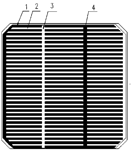
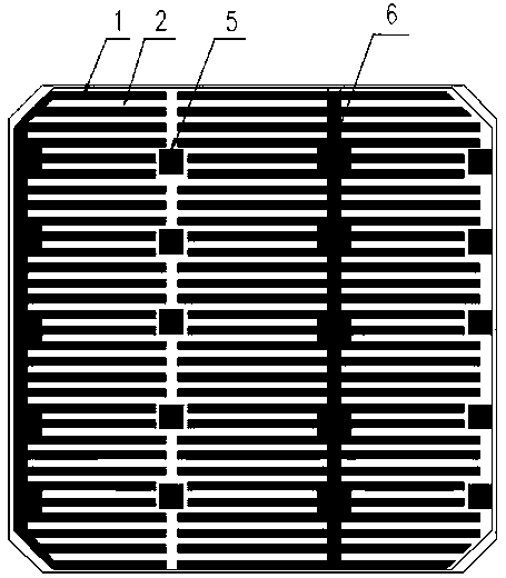
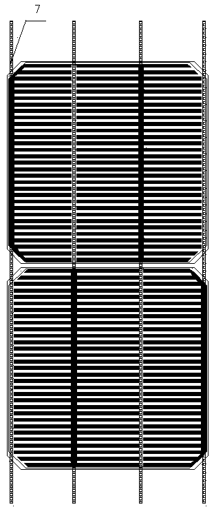
[0024] Embodiment 1, with reference to Figure 1-5 , a staggered back contact IBC solar cell electrode structure, the back of the cell is provided with interdigitated positive and negative grid electrodes (1, 2); the positive and negative grid electrodes (1, 2) pass through Insulation by laser etching or insulating glue; all the positive and negative grid electrodes (1, 2) on the back are respectively gathered on the strip or block positive and negative contact electrodes (3, 4, 5, 6); the positive and negative contact electrodes pass through The conductive welding strip 7 is connected, and the insulating adhesive film 8 is used to isolate and insulate between the conductive welding strip 7 and the block positive and negative grid line electrodes (5, 6).

Embodiment 2

[0025] Example 2, in the staggered back contact IBC solar cell electrode structure described in Example 1: the positive and negative grid electrodes (1, 2) are segmented electrodes that do not penetrate the entire surface of the cell.

Embodiment 3

[0026] Embodiment 3, in the staggered back contact IBC solar cell electrode structure described in Embodiment 1: the adjacent cells are rotated by 180°, and the positive and negative contact electrodes of the two cells are on a straight line.


PUM

PropertyMeasurementUnit
Thicknessaaaaaaaaaa
Widthaaaaaaaaaa

Abstract

The present invention relates to an electrode structure of an IBC solar cell. The electrode structure of the IBC solar cell is characterized in that inter-digital interlaced positive/negative grid line electrodes are arranged on the backside of the solar cell, the positive/negative grid line electrodes are insulated in a laser etching or insulation paste manner, and all the positive/negative grid line electrodes on the backside are gathered on the strip-like or block-like positive/negative contact electrodes respectively; the positive/negative contact electrodes are connected via conductive solder strips, and the conductive solder strips and the block-like positive/negative grid line electrodes are isolated and insulated via the insulation paste film. The positive/negative contact electrodes of the two solar cells can be in a straight line by rotating the adjacent solar cells 180 degrees and then placing the adjacent solar cells, and the IBC solar cells can be soldered and connected via the routine linear conductive solder strips, so that the electrode structure of the IBC solar cell is simple, convenient, safe, reliable, beautiful and practical and is suitable for the industrialization application, the photoelectric conversion efficiency of the large-size cells is improved, and the development from the IBC cell to the cell of 6 inches or a larger size is realized.

Description

technical field [0001] The invention relates to a solar cell, in particular to an electrode structure of an interlaced back contact IBC solar cell, which belongs to the field of solar photovoltaic technology. Background technique [0002] Solar energy is a clean, efficient, and inexhaustible new energy source. It is one of the important renewable energy sources. With the increasing energy crisis and environmental pollution, the development of renewable energy has become a strategic decision for sustainable energy development in countries all over the world. In solar energy applications, photovoltaic power generation is one of the important ways of solar energy applications, and its advantages of no noise, maintenance-free, and no emissions are gradually becoming popular. At present, crystalline silicon solar cells are mainly used in photovoltaic power generation. This is mainly because silicon materials are extremely abundant in the earth's crust. Photovoltaic power generati...

Claims


Application Information

Patent Timeline
IPC IPC(8): H01L31/0224
Inventor 何宝华何涛徐传明杜军伟王慧赵邦桂周利荣张忠卫
Owner LIANYUNGANG SHENZHOU NEW ENERGY
Why Eureka
Try Eureka