Electricity meter pulse modulation circuit and method
A technology of pulse modulation circuit and electric meter, which is applied in the direction of pulse frequency/rate modulation, measurement of electrical variables, measurement devices, etc., which can solve the problems of soft signal errors, inability to guarantee the continuity and integrity of signal transmission, etc.
- Summary
- Abstract
- Description
- Claims
- Application Information
AI Technical Summary
Problems solved by technology
Method used
Image
Examples
Embodiment Construction
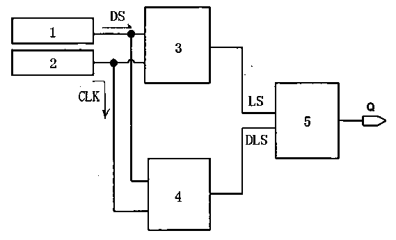
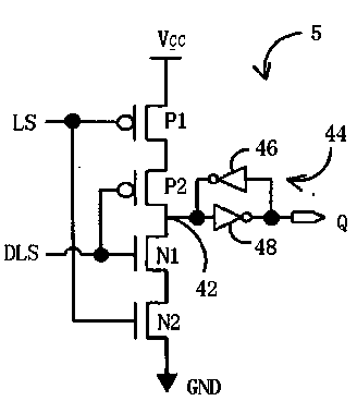
[0019] refer to figure 1 , a preferred embodiment of an ammeter pulse modulation circuit, used for the pulse waveform output by MCU1, it is coupled to MCU1 and ammeter clock source 2 and receives MCU data signal DS and clock pulse signal CLK respectively, including: a pulse latch section 3, for generating the latch signal LS according to the MCU data signal DS1 and the clock pulse signal CLK1; cutting the pulse latch part 4, for generating the cutting latch signal DLS according to the MCU1 data signal DS2 and the clock pulse signal CLK2; and coupling The output unit 5 is connected to the pulse latch unit 3 and the reduced pulse latch unit 4 and outputs a pulse signal Q.
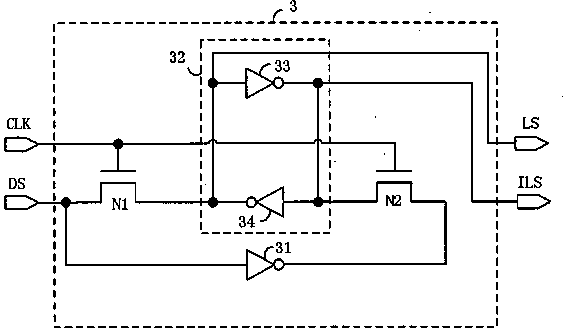
[0020] In one embodiment, the pulse latch unit 31 has a pulse input terminal DS and a clock input terminal CLK, similarly, the reduced pulse latch unit has a reduced pulse input terminal DS and a reduced clock input terminal CLK, wherein the The pulse input terminal and the cut pulse input terminal DS are co...
PUM
 Abstract
Description
Claims
Application Information
 - R&D
- Intellectual Property
- Life Sciences
- Materials
- Tech Scout
- Unparalleled Data Quality
- Higher Quality Content
- 60% Fewer Hallucinations
Browse by: Latest US Patents, China's latest patents, Technical Efficacy Thesaurus, Application Domain, Technology Topic, Popular Technical Reports.
© 2025 PatSnap. All rights reserved.Legal|Privacy policy|Modern Slavery Act Transparency Statement|Sitemap|About US| Contact US: help@patsnap.com


