
Laser cutting device and light splitting assembly thereof

A technology of spectroscopic components and spectroscopic mirrors, applied in the field of laser applications, can solve the problems of inconvenient adjustment of laser beam energy, cracks in cutting parts, and decline in product yield, and achieve the effects of improving cutting efficiency, improving yield, and reasonable energy distribution.

Active Publication Date: 2013-12-11
深圳市大族半导体装备科技有限公司
View PDF6 Cites 0 Cited by
  • Summary
  • Abstract
  • Description
  • Claims
  • Application Information

AI Technical Summary

Problems solved by technology

However, in the traditional laser cutting device, when the power is fixed, the power and spot size of the laser beam are fixed, which makes it inconvenient to adjust the energy of the laser beam
When cutting, if the energy of the laser beam is too large, it may cause cracks in the cutting part, resulting in a decrease in product yield

Method used


Image

  • Laser cutting device and light splitting assembly thereof
  • Laser cutting device and light splitting assembly thereof

Examples


Embodiment Construction

[0022] In order to facilitate the understanding of the present invention, the present invention will be described more fully below with reference to the associated drawings. Preferred embodiments of the invention are shown in the accompanying drawings. However, the present invention can be embodied in many different forms and is not limited to the embodiments described herein. On the contrary, these embodiments are provided to make the understanding of the disclosure of the present invention more thorough and comprehensive.

[0023] It should be noted that when an element is referred to as being “fixed” to another element, it can be directly on the other element or there can also be an intervening element. When an element is referred to as being "connected to" another element, it can be directly connected to the other element or intervening elements may also be present.

[0024] Unless otherwise defined, all technical and scientific terms used herein have the same meaning as...


PUM


Abstract

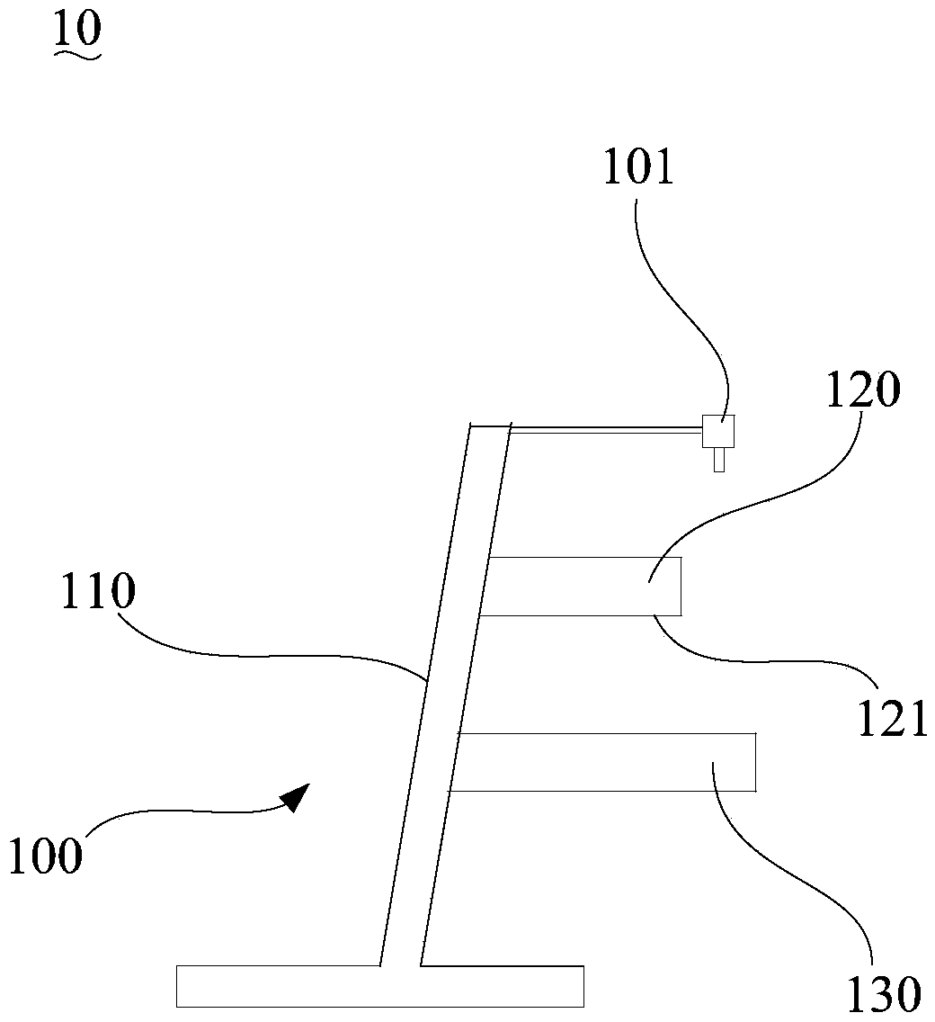
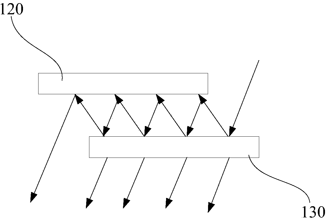
The invention discloses a laser cutting device and a light splitting assembly thereof. The light splitting assembly comprises a bracket, a reflecting mirror and a light splitting mirror, wherein the reflecting mirror and the light splitting mirror are parallel with each other and are arranged at intervals, and the light splitting mirror is arranged on one side, provided with a reflecting face, of the reflecting mirror. When laser beams illuminate the light splitting mirror in a preset angle, partial lights penetrate through the light splitting mirror, and the other lights are reflected to the reflecting mirror; after the lights are repeatedly reflected between the light splitting mirror and the reflecting mirror, the lights penetrating through the light splitting mirror form multiple groups of parallel emergent lights; the light splitting assembly can split the laser beams incident along the preset angle into multiple groups of parallel beams, and the energies of the beams are distributed according to a specific proportion, so that the energy distribution of light spots is more reasonable. Thus, when the laser cutting device is used for cutting, the light spots with the proper energies can be selected according to the requirements, and then the cutting yield is improved.

Description

technical field [0001] The invention relates to laser application technology, in particular to a laser cutting device and a light splitting component thereof. Background technique [0002] Traditional glass cutting adopts mechanical methods. With the continuous increase of market demand, the manufacturing industry has higher and higher requirements for production capacity, yield and glass quality. Mechanical methods are no longer suitable for the current process requirements. Laser cutting glass does not produce micro-cracks, which greatly improves the yield rate and saves the subsequent grinding process. Laser cutting not only improves production capacity, but also increases production efficiency. Therefore, laser glass cutting technology has become the future development direction, and will completely replace the existing mechanical cutting process in the near future. [0003] With the continuous development of the industry, the quality of glass cutting is also constantl...

Claims


Application Information

Patent Timeline
Patent Type & Authority Applications(China)
IPC IPC(8): B23K26/067C03B33/00
CPCY02P40/57
Inventor 柳啸杨名宇彭裕国高云峰
Owner 深圳市大族半导体装备科技有限公司
Learn More