Overhead cast-in-place box beam pressure-bearing strut and construction technology thereof

A box girder, cast-in-place technology, applied in bridges, bridge parts, bridge construction and other directions, can solve the problems of difficult to control the erection accuracy of the support platform, long construction time, low cost performance, etc., to achieve easy control of erection accuracy, short construction time, Inexpensive effect

Active Publication Date: 2013-12-11
CCCC SHEC FIRST HIGHWAY ENG
View PDF6 Cites 14 Cited by
  • Summary
  • Abstract
  • Description
  • Claims
  • Application Information

AI Technical Summary

Problems solved by technology

In the prior art, when it is necessary to erect a concrete box girder with a clearance height of about 30m, it is often used to set a high pressure bearing platform at the bottom of the box girder, and then place it on the pressure bearing platform. The box girder pressure-bearing pillars are erected on the platform. The cast-in-place box girder erection in this way not only has the disadvantages of labor-intensive, time-consuming, and high material consumption, but also the erection accuracy of the erected support platform is difficult to control, that is, the existing technology has low cost performance and poor construction efficiency. Shortcomings that take a long time and cannot meet the requirements of modern engineering

Method used


Image

  • Overhead cast-in-place box beam pressure-bearing strut and construction technology thereof
  • Overhead cast-in-place box beam pressure-bearing strut and construction technology thereof
  • Overhead cast-in-place box beam pressure-bearing strut and construction technology thereof

Examples


Embodiment Construction

[0034] The implementation of the present invention will be described in detail below in conjunction with the accompanying drawings, but they do not constitute a limitation to the present invention, and are only examples. At the same time, the advantages of the present invention are clearer and easier to understand through the description.

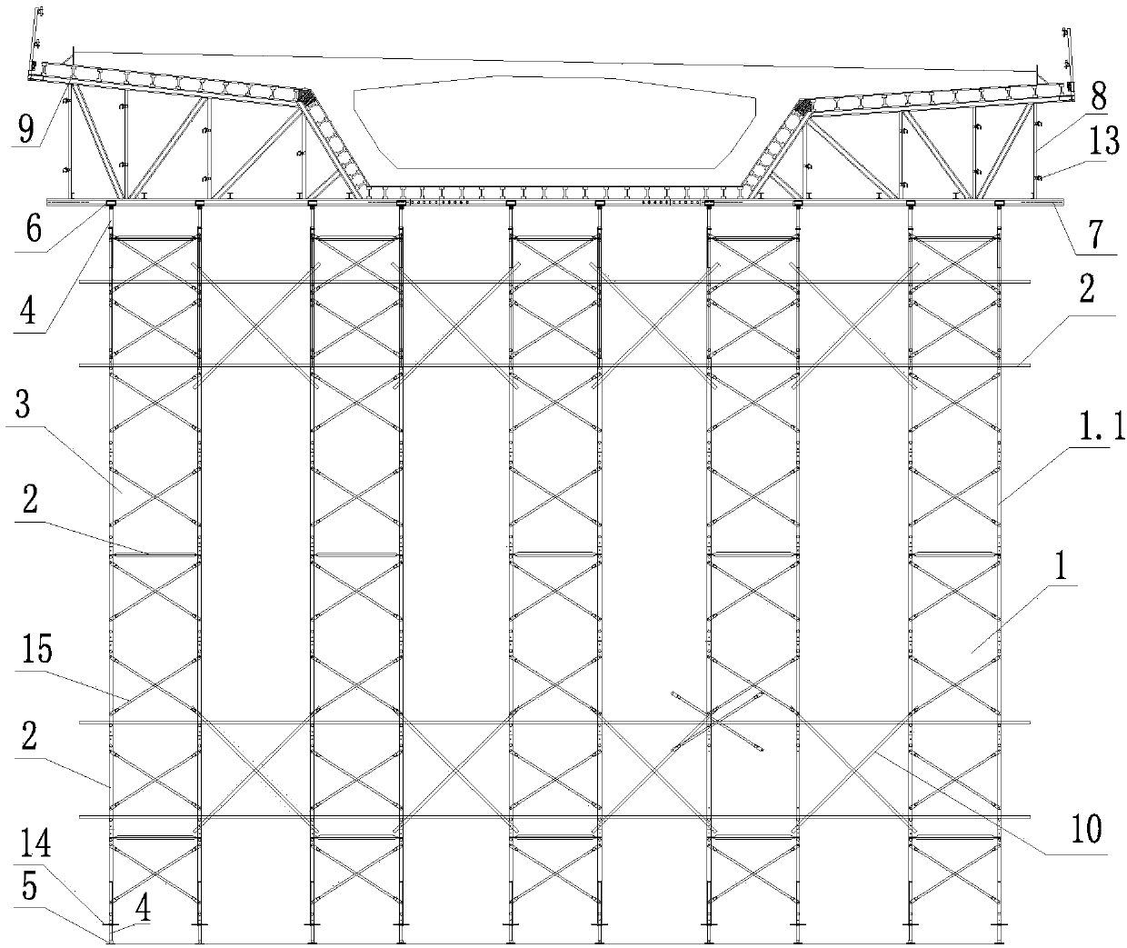
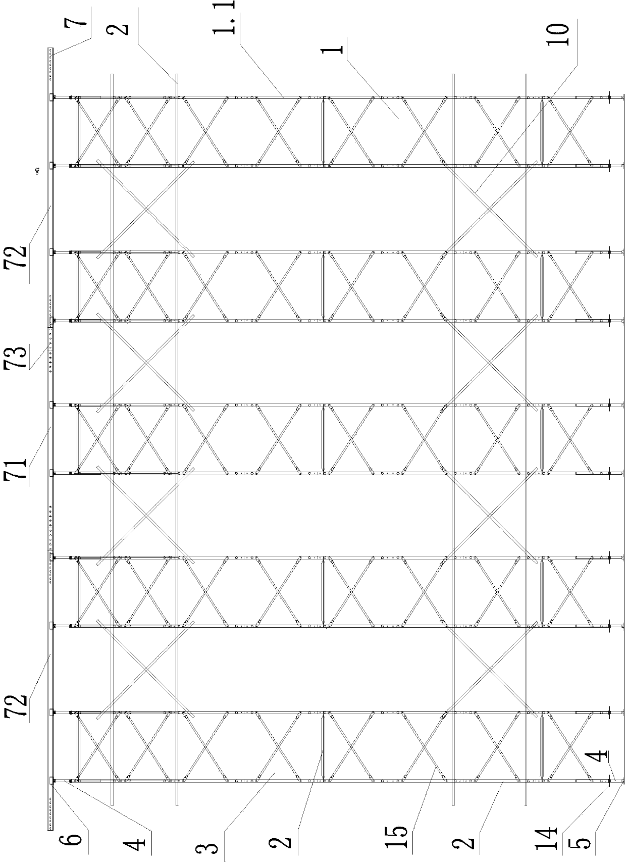
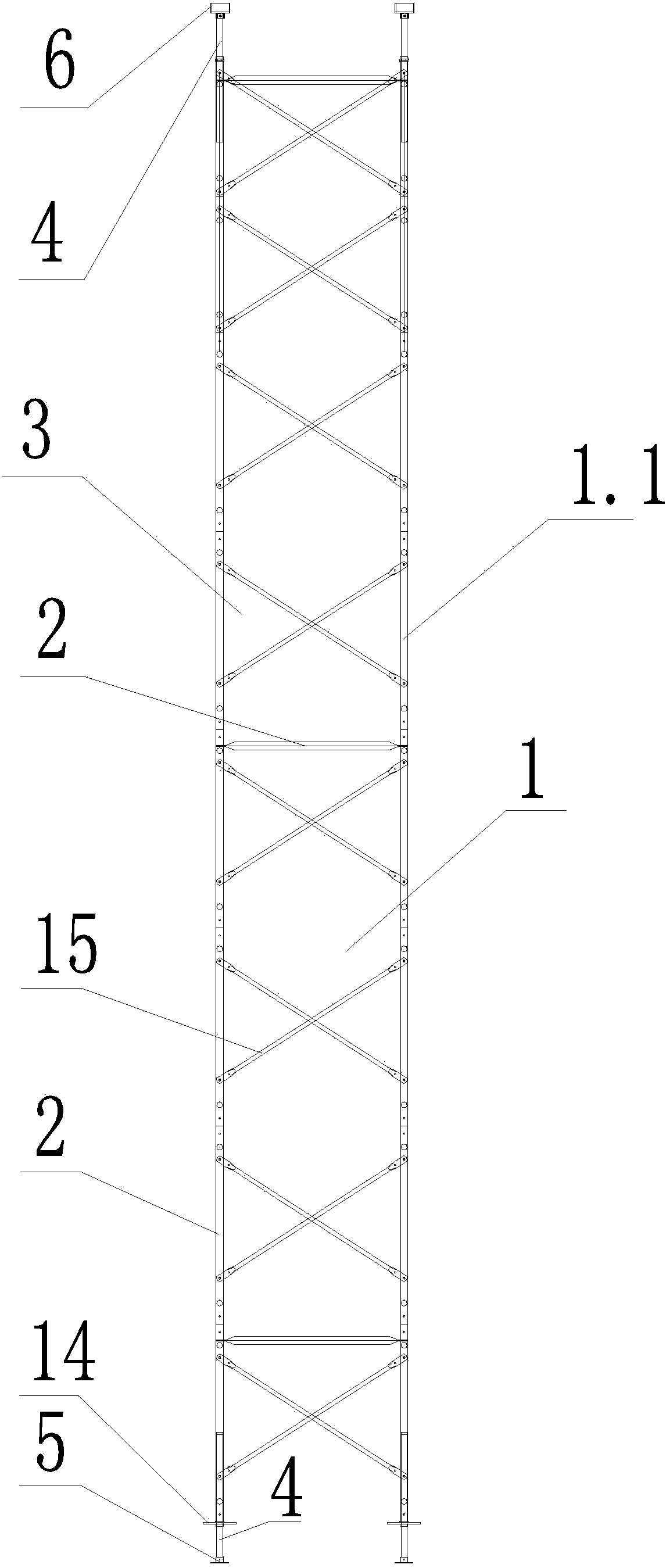
[0035] Referring to the accompanying drawings, it can be seen that the high-altitude cast-in-place box girder pressure-bearing pillars include several bracket bodies 1 with vertical support rods 1.1, and also include transverse stiffening brackets 2 connected to the side walls of the bracket body 1. The bracket body 1 is composed of multiple Two scaffolds 3 arranged up and down are composed, and cross brackets 10 are connected between adjacent bracket main bodies 1; the top and bottom ends of the vertical support bar 1.1 are respectively equipped with a support 5 and a bracket 6, and the support 5 The middle part of the bracket and the midd...


PUM


Abstract

The invention discloses an overhead cast-in-place box beam pressure-bearing strut and relates to overhead concrete box beam hole-by-hole casting construction work. The overhead cast-in-place box beam pressure-bearing strut comprises a support body (1), a reinforced support (2) and a crossed support (10). The support body (1) is composed of a plurality of scaffolds (3). A supporting base (5) and a bracket (6) are arranged at the top end and the bottom end of a vertical supporting rod (1.1) respectively. The bracket (6) is provided with distribution beams (7) in an overlapped mode, and the distribution beams (7) comprise a first distribution beam (7.1) placed in the middle and second distribution beams (7.2) placed on two sides. The second distribution beams (7.2) are provided with wing plate supports (8) in an overlapped mode, and the first distribution beam (7.1) and the wing plate supports (8) are provided with formworks (9) in an overlapped mode. The overhead cast-in-place box beam pressure-bearing strut is convenient to assemble and disassemble, high in mechanical degree, quick in transferring, and capable of improving construction efficiency of cast-in-place box beams. According to the overhead cast-in-place box beam pressure-bearing strut, overlapping accuracy of the support body can be controlled easily, cost performance is high, construction time is short, and modern construction demands can be met. The invention further discloses a construction technology of the overhead cast-in-place box beam pressure-bearing strut.

Description

technical field [0001] The invention relates to a hole-by-hole pouring construction project of a high-altitude concrete box girder, in particular to a high-altitude cast-in-place box girder pressure pillar, and also relates to a construction process for the high-altitude cast-in-place box girder pressure pillar. Background technique [0002] With the continuous development of highways and high-speed railways in my country, it is a trend for cast-in-place box girders to develop towards high altitudes and large spans. In the prior art, when it is necessary to erect a concrete box girder with a clearance height of about 30m, it is often used to set a high pressure bearing platform at the bottom of the box girder, and then place it on the pressure bearing platform. The box girder pressure-bearing pillars are erected on the platform. The cast-in-place box girder erection in this way not only has the disadvantages of labor-intensive, time-consuming, and high material consumption, ...

Claims


Application Information

Patent Timeline
Patent Type & Authority Applications(China)
IPC IPC(8): E01D19/00E01D21/00
Inventor 张钊潘中明陈干赵军科田新平陈杰
Owner CCCC SHEC FIRST HIGHWAY ENG
Why Eureka
Try Eureka