A Branched Film Hole Structure for Gas Turbine Engine Cooling

A technology of engine cooling and gas turbine, which is applied in the direction of engine cooling, turbine/propulsion device cooling, engine function, etc., which can solve the problems of weak cooling coverage effect and large cooling air consumption, etc., to increase coverage and process Low cost, good cooling effect

Active Publication Date: 2016-03-30
TSINGHUA UNIV
View PDF7 Cites 0 Cited by
  • Summary
  • Abstract
  • Description
  • Claims
  • Application Information

AI Technical Summary

Problems solved by technology

[0003] Chinese patent document (CN201110020609.1) discloses a double-jet hole cooling structure for an air-cooled turbine. The technical solution is to arrange circular cross-section air film holes in pairs, and use the mutual interference formed by the two to improve the air film cooling effect. Its cooling effect under the condition of high blowing ratio is obviously better than that of a single row of round holes, but its disadvantage is that the doubled number of holes leads to a large cooling air consumption
Chinese patent document (CN201010131826.3 discloses a new type of air film hole (main hole + vortex suppression branch hole structure) with a vortex suppressing branch hole structure. The air film hole suppresses the main hole through the secondary airflow generated by the symmetrical branch hole The kidney-shaped vortex of the airflow improves the cooling effect of the airflow in the main hole at a high blowing ratio, but research shows that its cooling coverage effect is still weaker than that of the double-jet hole structure at a high blowing ratio

Method used


Image

  • A Branched Film Hole Structure for Gas Turbine Engine Cooling
  • A Branched Film Hole Structure for Gas Turbine Engine Cooling
  • A Branched Film Hole Structure for Gas Turbine Engine Cooling

Examples


Embodiment Construction

[0017] Structure, principle and performance of the present invention are described below in conjunction with accompanying drawing:

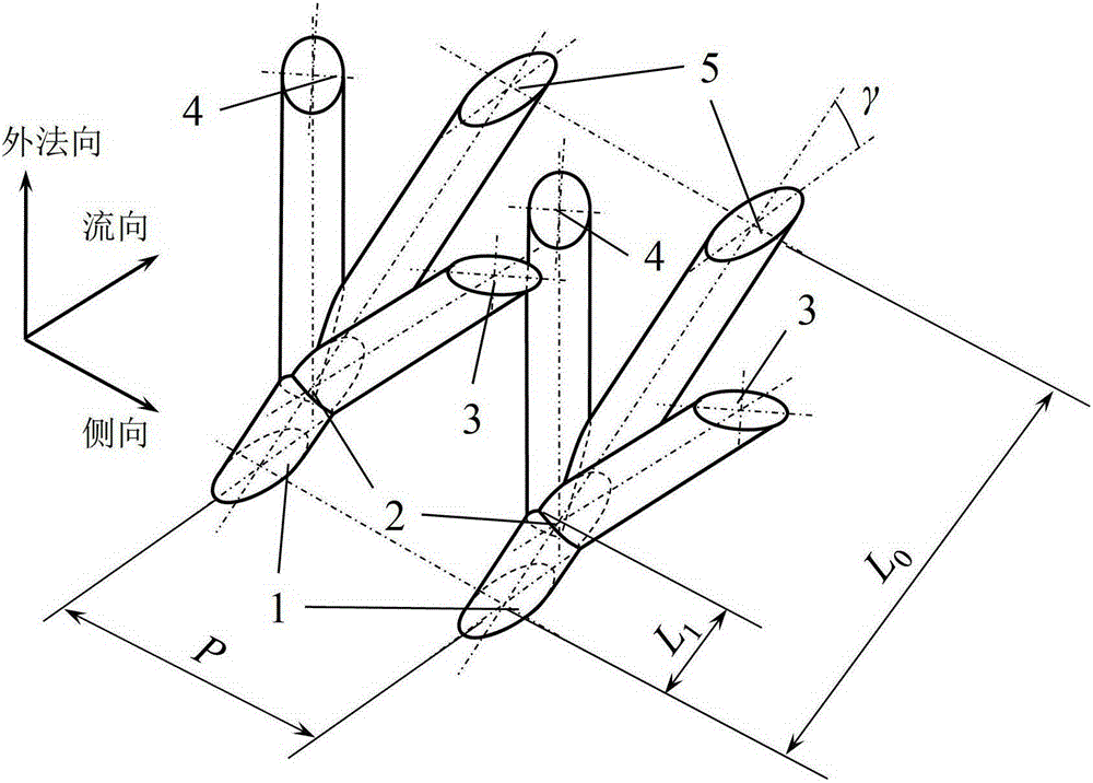
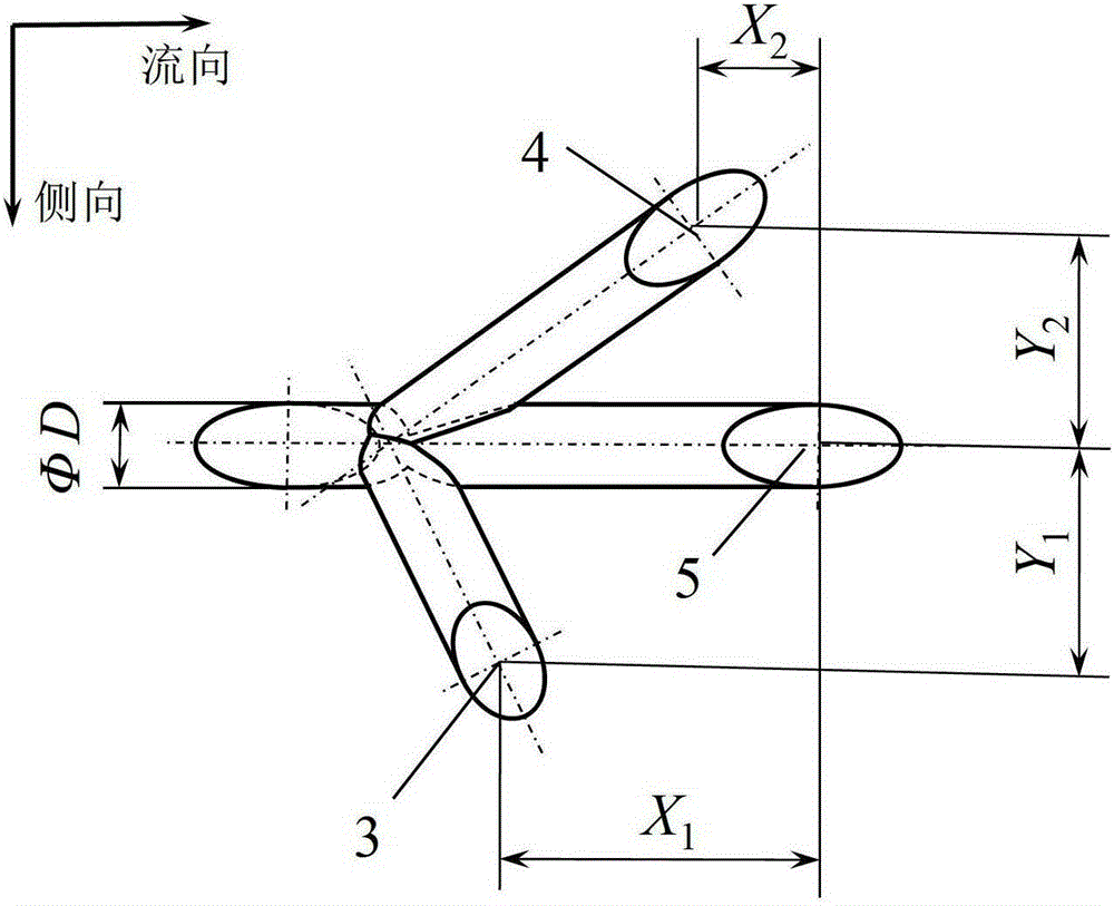
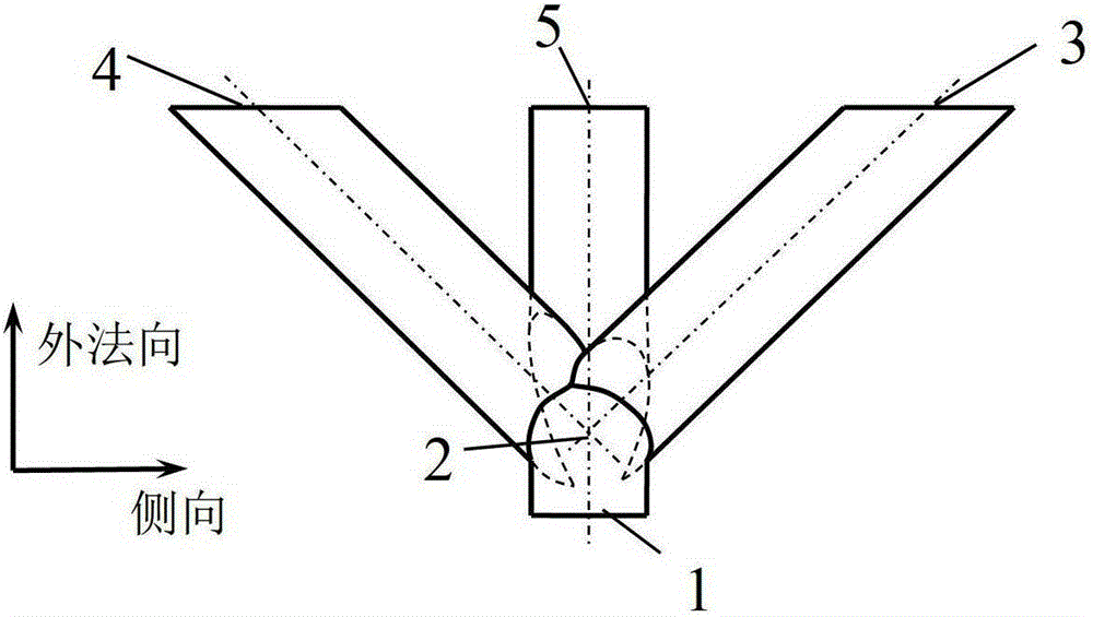
[0018] The present invention is a kind of branch gas film hole structure that is used for the cooling of gas turbine engine, and the basic geometrical feature of its through-flow part is as follows: figure 1 , figure 2 and image 3 shown. The basic geometric structure of the branch film cooling includes the main hole entrance 1, the bifurcation position 2, the first branch hole 3, the second branch hole 4 and the main hole outlet 5; the branch film holes are arranged in rows to form a film hole row structure The main hole is a straight hole with a circular cross-section; the first branch hole outlet 3 and the second branch hole outlet 4 are respectively connected to the gas film hole bifurcation position 2 through a circular cross-section straight hole; the main hole outlet 5, the first branch hole outlet 3 and the second branch hole outlet 4...


PUM


Abstract

The invention provides a branch gas film hole structure for cooling a gas turbine engine, which is applicable to cooling high-temperature components such as a combustion chamber and a turbine of the gas turbine engine. Branch gas film holes are formed equidistantly in rows; each branch gas film hole comprises a main hole, a first branch hole and a second branch hole; the holes are straight holes with circular sections; the two branch holes are connected with the main hole in the same position in each branch gas film hole; and positions of flow directions of the first branch holes and the second branch holes are in tandem, so that the first branch hole of each branch gas film hole and the second branch hole of the adjacent branch gas film hole form mutual interference. According to the branch gas film hole structure, an outlet area is increased by the branch holes; a gas film cooling coverage area is increased; a flow field structure facilitating gas film cooling coverage is constructed due to the mutual interference among the branch holes of the adjacent branch gas film holes; and a cooling fluid has a better coverage effect on a wall surface.

Description

technical field [0001] The invention relates to a gas turbine engine, specifically including heavy-duty gas turbines for power generation, aeroengines, and ship gas turbines. The film cooling efficiency of high-temperature components such as combustion chambers, etc., is suitable for film cooling of all discrete hole forms. Background technique [0002] The operating temperature of modern gas turbine engines has exceeded the withstand temperature of metallic materials. As an efficient cooling method, film cooling is widely used in the cooling of high-temperature components of heavy-duty gas turbines, aero-engines and ship gas turbines. Film cooling is the jet flow of cooling gas from one or more discrete holes to form a gas film on the wall to protect the wall from being ablated by high temperature gas. In a gas turbine engine, the air used for cooling is generally compressed air extracted from the corresponding stage of the compressor. The efficiency of film cooling is di...

Claims


Application Information

Patent Timeline
Patent Type & Authority Patents(China)
IPC IPC(8): F02C7/18
CPCF01D5/186F01D9/065F05D2240/81F05D2260/202F23R3/002F23R2900/03041F23R2900/03042
Inventor 蒋洪德任静迟重然
Owner TSINGHUA UNIV
Why Eureka
Try Eureka