RFID (radio frequency identification) reader based on adaptive smart antennae

A smart antenna and reader technology, applied in the field of radio frequency identification, can solve problems such as limited effective identification area, unrecognized tags, lost tags, etc., to improve the degree of digitization and self-adaptive ability, expand the effective identification area, and increase the maximum identification effect of distance

Inactive Publication Date: 2013-12-11
TIANJIN POLYTECHNIC UNIV
View PDF3 Cites 11 Cited by
  • Summary
  • Abstract
  • Description
  • Claims
  • Application Information

AI Technical Summary

Problems solved by technology

[0004] (1) In the passive UHF RFID system, the maximum recognition distance of a reader is about 10 meters, and the total effective recognition area is limited, which cannot meet the needs of most users
[0005] (2) In the UHF RFID system, a key problem is that it is difficult to achieve 100% recognition rate, that is, some tags are not recognized, that is, the problem of missing tags
In terms of hardware, there are two main reasons for the problem of lost tags: First, the effective identification area of ​​passive RFID systems is limited because of the limited transmit power of the antenna and the fixed radiat

Method used


Image

  • RFID (radio frequency identification) reader based on adaptive smart antennae
  • RFID (radio frequency identification) reader based on adaptive smart antennae
  • RFID (radio frequency identification) reader based on adaptive smart antennae

Examples


Embodiment Construction

[0027] In order to more clearly illustrate the technical solutions in the embodiments of the invention or the prior art, the following will briefly introduce the drawings that need to be used in the description of the embodiments or the prior art. Obviously, the drawings in the following description are only For some embodiments of the present invention, those skilled in the art can also obtain other designs according to the drawings without paying creative labor.

[0028] In order to make the object, technical solution and advantages of the present invention clearer, the embodiments of the present invention will be further described in detail below in conjunction with the accompanying drawings, but the embodiments of the present invention are not limited thereto.

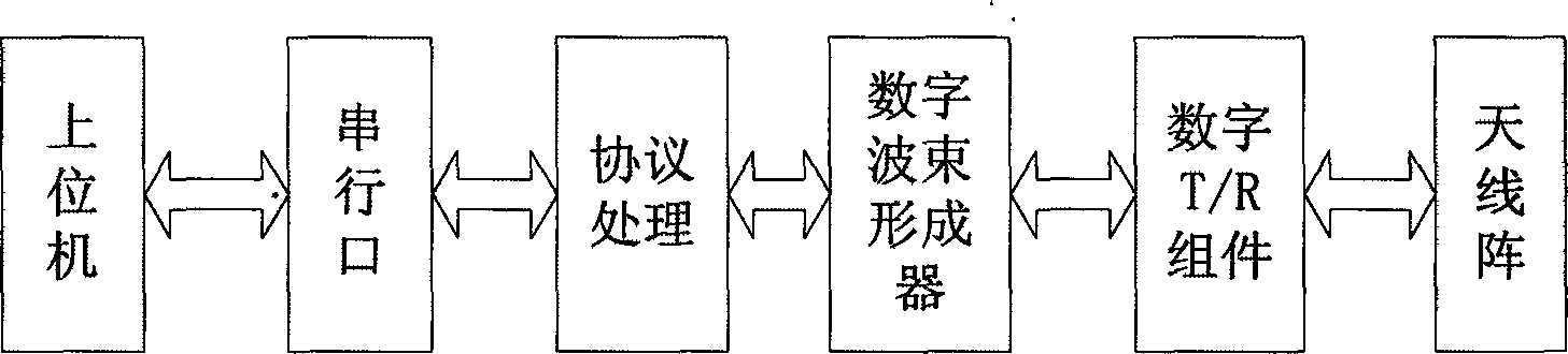
[0029] Such as figure 1 As shown, the reader includes a protocol processing module, a digital beamformer, a digital transmission / reception component (T / R component) and an antenna array composed of multiple antenna...


PUM


Abstract

The invention discloses an RFID (radio frequency identification) reader based on adaptive smart antennae, belonging to the technical field of radio frequency identification. The RFID reader comprises a protocol processing module, a digital beam former, a digital transmitting/receiving component (T/R) component) and an antenna array consisting of a plurality of antenna elements, wherein the protocol processing module comprises coding, decoding and protocol processing; the digital beam former comprises an optimal weight generating network and an adaptive beam forming network; and the T/R component comprises a DDS (direct digital synthesizer), an upper frequency converter, a lower frequency converter, a filter, a power amplifier, a circulator and an A/D (analog-to-digital) sampling unit. The RFID reader disclosed by the invention can ensure that antenna beam main lobes point to a useful signal direction and null or lower side lobes point to an interference signal direction, so that the identification range of the reader is expanded and the interference resistance of the reader is improved.

Description

technical field [0001] The invention relates to a radio frequency identification (RFID) technology, in particular to an RFID reader. Background technique [0002] With the development of information technology, the Internet of Things has developed into a new industry. As one of the foundations of the Internet of Things, Radio Frequency Identification (RFID) technology has become a technology that people pay more and more attention to. The RFID system is mainly composed of three parts: transponder (radio frequency card and electronic tag), reader (reader and base station) and host computer system (middleware and network application). In the radio frequency identification system, according to the different structures of the electronic tag power supply system, RFID electronic tags are mainly divided into active tags, semi-active tags and passive tags. Active tags and semi-active tags have an external battery, which provides energy for the work of the tag chip. The advantage is...

Claims


Application Information

Patent Timeline
IPC IPC(8): G06K7/00
Inventor 李建雄陈晓宇肖康刘崇李运祥袁文东
Owner TIANJIN POLYTECHNIC UNIV
Why Eureka
Try Eureka