An Antenna Structure for Contactless Communication

An antenna structure and non-contact technology, which is applied in the field of antenna structure, can solve the problems of making the size of the card reader smaller, increasing the difficulty, and making it difficult to make the size of the card reader smaller, so as to achieve the reduction of the size of the planar structure, the concentration of the magnetic field, and the improvement of Effects of Communication Strength and Reliability

Active Publication Date: 2015-09-16
SHENZHEN XINGUODU PAYMENT TECH CO LTD
View PDF3 Cites 0 Cited by
  • Summary
  • Abstract
  • Description
  • Claims
  • Application Information

AI Technical Summary

Problems solved by technology

The size of a standard contactless card is 85.5mm×54mm, so it is difficult to make the size of the card reader smaller in the current solution
The inability to reduce the size of the card reader increases the difficulty of integrating this function into electronic devices

Method used


Image

  • An Antenna Structure for Contactless Communication
  • An Antenna Structure for Contactless Communication
  • An Antenna Structure for Contactless Communication

Examples


Embodiment Construction

[0030] In order to fully understand the technical content of the present invention, the technical solutions of the present invention will be further introduced and illustrated below in conjunction with specific examples, but not limited thereto.

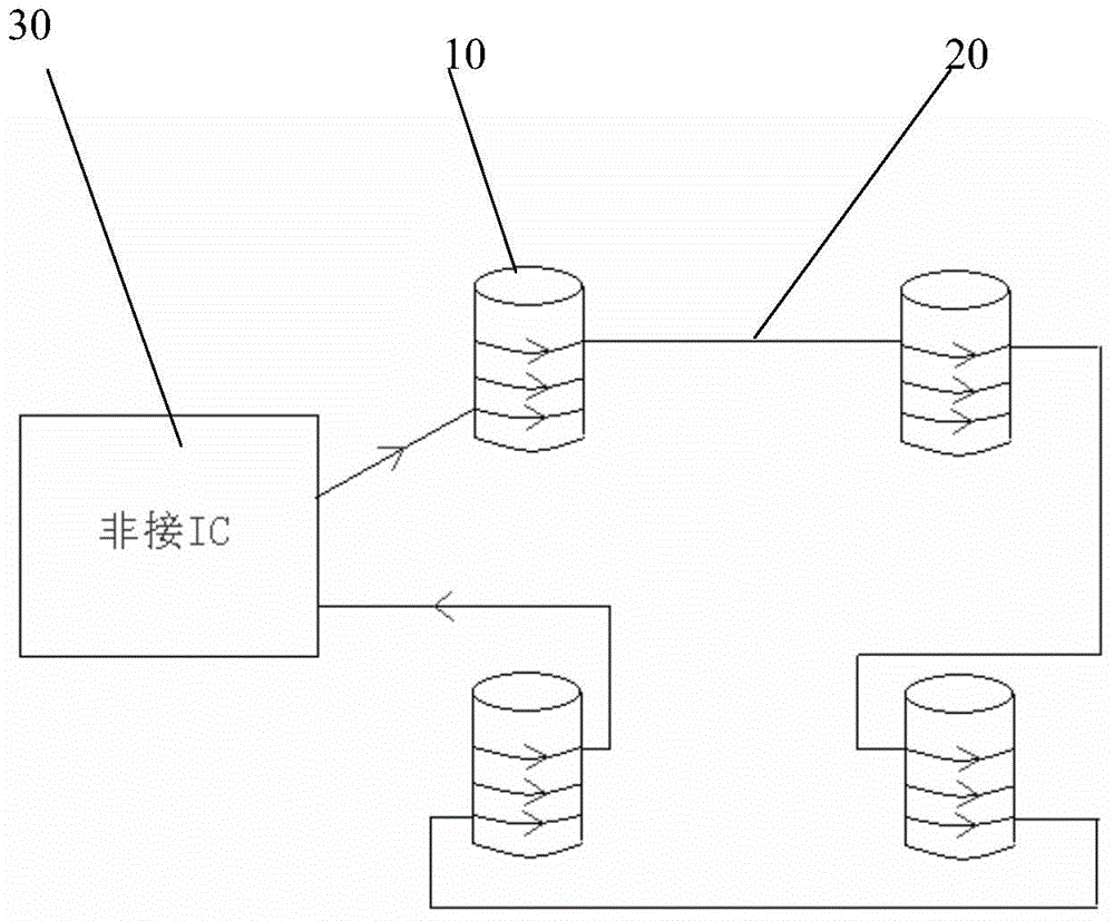
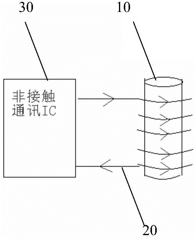
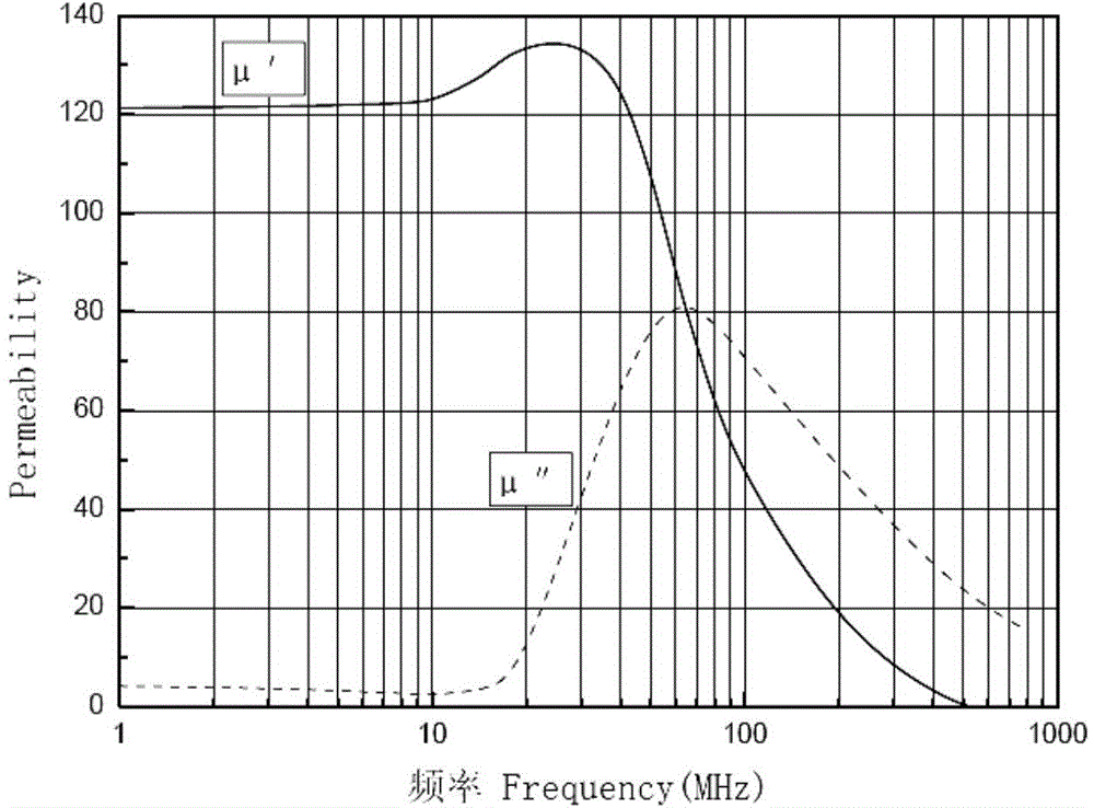
[0031] Such as figure 1 The specific embodiment 1 shown is an antenna structure for non-contact communication of the present invention, including a magnetic conductor 10, and an electric wire 20 (that is, as an antenna conductor) wound around the outer periphery of the magnetic conductor 10. The electric wire 20 and the The non-contact communication IC circuit 30 is connected; the magnetic conductor 10 is cylindrical, and the magnetic conductor is made of ferrite, and the nickel-zinc ferrite is nickel-zinc ferrite with a magnetic permeability of 100 or more at a frequency of 13.56MHz. Its resistivity is 10 5 Ω*m; the working frequency of the antenna structure is 10-20MHz. from image 3 The magnetic permeability curve of nickel-zin...


PUM


Abstract

The invention discloses an antenna structure for non-contact communication. The antenna structure for non-contact communication comprises a magnetizer and an electric wire wound around the periphery of the magnetizer. The electric wire is connected with a non-contact communication IC. The magnetizer is cylindrical. According to the antenna structure for non-contact communication, the cylindrical magnetizer is used as a magnetic core of an antenna, so that the plane structure size of the antenna is greatly reduced, the original size larger than 85.5mm*54mm is reduced to the size smaller than 50mm*50mm, the size of a card reader is reduced to a large extent, and possibility of the integration and the miniaturization of non-contact communication products is provided. In addition, due to the adoption of a magnetizer material, the diameter of the magnetizer is small, the number of winding circles of the electric wire can be increased, the intensity of magnetic fields is increased, the magnetic fields are concentrated, the improvement of the communication intensity and the reliability of a non-contact communication card is facilitated, and the application of a specially-shaped non-contact communication card and the miniaturization development of the non-contact communication products are facilitated.

Description

technical field [0001] The present invention relates to an antenna structure, more specifically to an antenna structure for non-contact communication. Background technique [0002] As people communicate more and more frequently, there are more and more cash transactions. People have to carry a lot of cash, which brings people a lot of unnecessary troubles. One is the inconvenience caused by carrying a large amount of cash, and the other is All kinds of risks brought by carrying a large amount of cash, so various bank cards have emerged as the times require. The existing bank cards mainly include non-contact IC cards, magnetic stripe cards and contact IC cards. Now most contactless IC cards are mainly used in micropayment or fields that require simple authentication, such as bus cards, subway cards, meal cards and access control cards. [0003] Non-contact IC card, also known as radio frequency card or RF card, is composed of IC chip and induction antenna, which are package...

Claims


Application Information

Patent Timeline
Patent Type & Authority Patents(China)
IPC IPC(8): H01Q7/08H01Q1/36H01Q1/22G06K19/067
Inventor 翟建光甘彦君李伟光
Owner SHENZHEN XINGUODU PAYMENT TECH CO LTD
Why Eureka
Try Eureka