Temporary grounding device and grounding method for distribution box substation

A temporary grounding and grounding method technology, applied in the direction of grounding devices, can solve problems such as difficult grounding implementation, poor grounding effect, and extended repair time, so as to improve installation efficiency and grounding reliability, avoid personal induction accidents, and simplify The effect of the installation process

Active Publication Date: 2015-09-23
ANSHAN POWER SUPPLY COMPANY OF STATE GRID LIAONING ELECTRIC POWER COMPANY +1
View PDF5 Cites 7 Cited by
  • Summary
  • Abstract
  • Description
  • Claims
  • Application Information

AI Technical Summary

Problems solved by technology

With the development of power grid technology, new distribution box substations are generally equipped with grounding devices (such as grounding switches, grounding switches), but most urban areas still operate old-fashioned distribution box substations that need to be upgraded. The traditional grounding wires need to be installed for box transformer maintenance and emergency repairs. The disadvantages are: 1) The grounding end of the grounding wire: some are directly inserted into the ground with iron brazing, which is affected by winter and the natural environment (cement and asphalt pavement, etc.) It is difficult to implement grounding, which needs to be completed with the help of tools, and the grounding effect is not good, and the discharge is not complete
When preparing tools for emergency repair, once the grounding wire is not properly prepared, it is difficult to mount it firmly, and it cannot guarantee that the three-phase reliable short circuit will affect the continued work, prolong the emergency repair time, and reduce work efficiency.
3) The grounding wire lacks a grounding discharge monitoring process, and the conductors of the three phases A, B, and C are prone to false connections, resulting in leakage discharges and potential safety hazards for maintenance operators
Therefore, it is urgent to develop a new type of temporary grounding device and grounding method to solve and make up for the grounding defects during the operation of the distribution box and the emergency repair of the accident.

Method used


Image

  • Temporary grounding device and grounding method for distribution box substation
  • Temporary grounding device and grounding method for distribution box substation
  • Temporary grounding device and grounding method for distribution box substation

Examples


Embodiment Construction

[0018] The specific embodiment of the present invention will be further described below in conjunction with accompanying drawing:

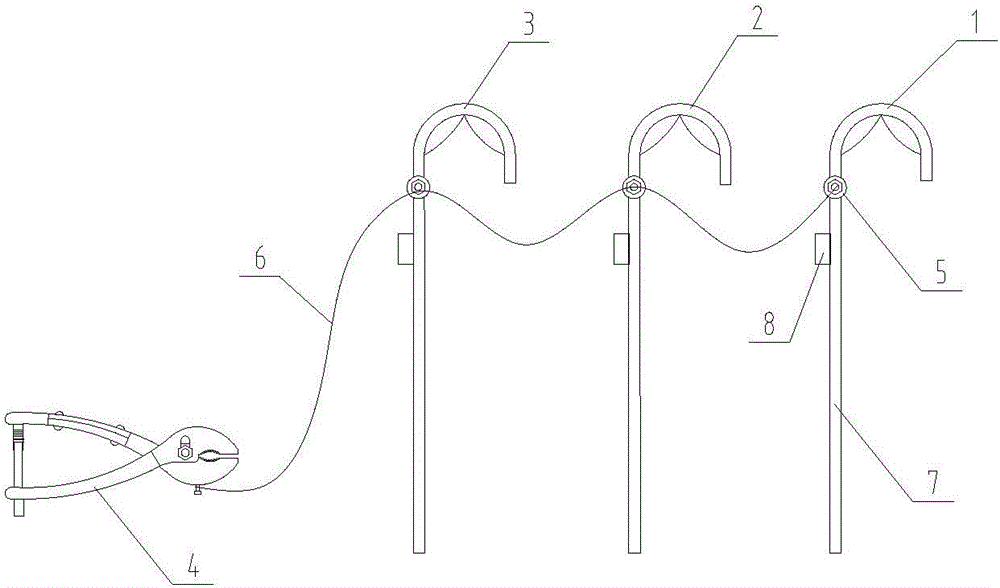
[0019] See figure 1 , is a structural schematic diagram of an embodiment of a temporary grounding device for a distribution box substation according to the present invention, including a conductor hook-up piece 1, a conductor hook-up piece 2, and a conductor hook-up piece 3 for A, B, and C three-phase buses And the clamp 4 that is fixed with the ground terminal, the conductor hook one 1, the conductor hook two 2, the conductor hook three 3 and the wire clamp 4 are connected successively by soft copper wire 6, the conductor hook one 1, the conductor Mounting part 2 and conductor mounting part 3 are respectively fixed on the top of the insulating rod 7 through the movable contact 5, and the movable contact 5 can adjust the direction of the mounting point according to the types of various high-voltage busbars in the distribution box to improve the co...


PUM


Abstract

The invention relates to the field of temporary grounding, in particular to a temporary grounding device of a distribution box substation and a grounding method. The temporary grounding device of the distribution box substation is characterized in that when discharging is carried out on a phase A, a phase B and a phase C, a discharging caution link is added. The grounding method comprises the following specific steps of (1) carrying out a check to ensure that conductor hanging parts and a wire clamp are reliably connected with a soft copper wire, and insulating rods meet the requirement for insulation; (2) carrying out a check on a live wire according to the requirements of site rules before operation; (3) hanging the first conductor hanging part on a bus of the phase A after the wire clamp is grounded, wherein when a reliable connecting loop is formed by a bus of the distribution box substation and a ground wire, a discharging indication alarm device on the first conductor hanging part can give out sounds with high decibel to low decibel, when sounds are not given out, or the given sounds are intermittent, a hanging point is in poor contact, and discharging of the phase B or the phase C is carried out after discharging of the bus of the phase A is accomplished. Compared with the prior art, the temporary grounding device of the distribution box substation and the grounding method have the advantages that convenience of operation of temporary grounding and reliability of grounding are ensured, and the installing efficiency of the ground wire is improved when an electric power circuit is in outage operation.

Description

technical field [0001] The invention relates to the field of temporary grounding in power system blackout operations, in particular to a temporary grounding device and grounding method for distribution box transformer operations and accident repairs. Background technique [0002] The function of installing the grounding wire in the power system is: 1) a reliable safety measure to prevent the workplace from being injured by a sudden power call; 2) to discharge the remaining charge of the maintenance equipment; 3) to eliminate the induced static electricity of the maintenance equipment. It is an important technical measure for the power system to prevent workers from being electrocuted and ensure the safety of workers. With the development of power grid technology, new distribution box substations are generally equipped with grounding devices (such as grounding switches, grounding switches), but most urban areas still operate old-fashioned distribution box substations that nee...

Claims


Application Information

Patent Timeline
Patent Type & Authority Patents(China)
IPC IPC(8): H02B1/16
Inventor 孙道军杨印刘天东孙超尚尔军王刚张连贵韩济阳
Owner ANSHAN POWER SUPPLY COMPANY OF STATE GRID LIAONING ELECTRIC POWER COMPANY
Why Eureka
Try Eureka