Resonance-type power electronic current transformer and current transformer device

A technology of power electronics and converters, which is applied in the direction of high-efficiency power electronics conversion, adjustment of electric variables, and output power conversion devices, etc. It can solve the problems of unable to meet the new needs of the power system, large volume of industrial frequency transformers, and low reliability. , achieve high-efficiency energy transfer and intelligent control, wide output voltage range, and reduce switching loss

Active Publication Date: 2013-12-11
ZHEJIANG UNIV
View PDF5 Cites 38 Cited by
  • Summary
  • Abstract
  • Description
  • Claims
  • Application Information

AI Technical Summary

Problems solved by technology

However, limited by the current development level of power electronic devices, this architecture also requires a power frequency distribution transformer to match the output of the bidirectional power electronic converter and the AC bus voltage
[0004] Although the production process of industrial frequency transformers is simple and the price is low, industrial frequency transformers are large in size, heavy in weight, and do not have the ability to isolate faults. At the same time, the power frequency transformer cannot maintain the stability of the secondary side voltage, and cannot realize the automatic adjustment and intelligent management of energy, which has become increasingly unable to meet the new needs raised in the development of the power system, such as the smart grid
[0005] In order to flexibly control the energy flow in the power grid, effectively utilize new energy sources, and reduce the size of transformers, scholars have proposed some solutions, such as the EU's

Method used


Image

  • Resonance-type power electronic current transformer and current transformer device
  • Resonance-type power electronic current transformer and current transformer device
  • Resonance-type power electronic current transformer and current transformer device

Examples


Embodiment Construction

[0045] The present invention will be further described below in conjunction with the accompanying drawings and specific embodiments.

[0046] First of all, explain: the "high frequency" mentioned in the present invention refers to several kilohertz to tens of kilohertz; the "high voltage" mentioned refers to tens of kilovolts to hundreds of kilovolts, or even higher. The circuit or component using this qualifier in the name refers to the circuit or component that can realize the corresponding function or be used in the corresponding environment. This concept belongs to the basic concept of this field, which is well known to those skilled in the art, so the present invention will not repeat it.

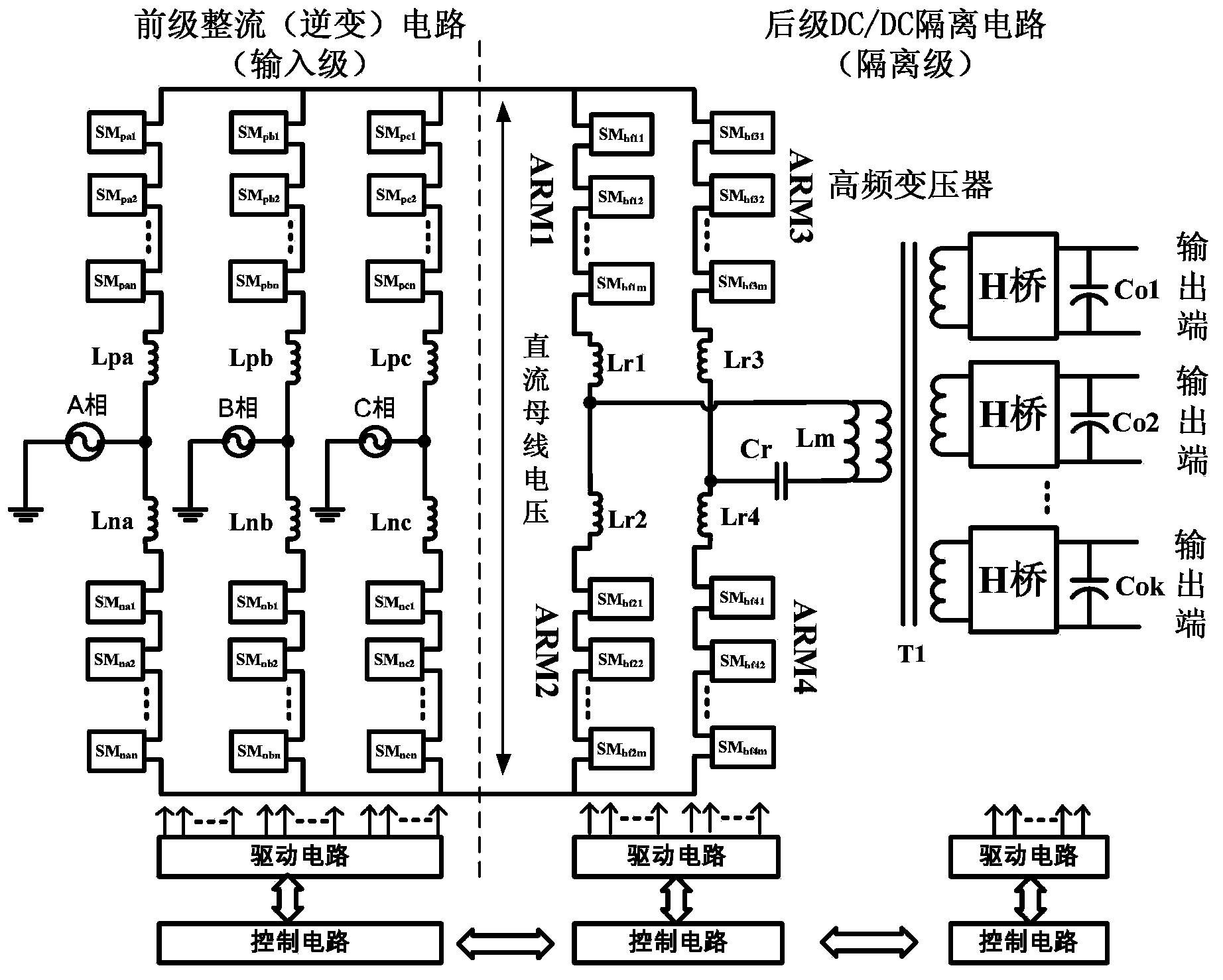
[0047] refer to figure 1 , the entire converter system includes a two-stage structure of input stage and isolation stage, in which the front stage is a three-phase rectification (inversion) circuit, and the latter stage is a resonant DC / DC circuit with high-frequency isolation that ca...


PUM


Abstract

The invention relates to the technical field of power electronic current transformers, and provides a resonance-type power electronic current transformer and a current transformer device. The current transformer comprises an input-stage rectifying circuit and a rear-stage DC/DC circuit. The input-stage rectifying circuit comprises three bridge arms. Each bridge arm is composed of an upper half bridge arm body and a lower half bridge arm body. The midpoints of the bridge arms are connected with three phases of a high-voltage alternating-current power grid respectively. Each half bridge arm body comprises n module units. Ports of the module units are connected in a head-to-tail mode to form a bridge arm structure. Due to the high-frequency isolation of the input side and the output side, a heavy lower-frequency transformer is removed, and meanwhile efficient energy transmission and intelligent control are achieved. Harmonic wave transmission between different power grids and mutual influences caused by failures of the different power grids can be intercepted, meanwhile, the range of the output voltage is wide, continuous adjustment of the current and the voltage can be achieved, system operation information of the current transformer is easy and convenient to collect, mutual communication can be achieved among a plurality of current transformer systems, and the intelligent power grid is obtained.

Description

technical field [0001] The invention relates to the technical field of power electronic converters, in particular to a power electronic converter system capable of realizing high efficiency, high-frequency isolation, high-voltage input, wide-range stable voltage output, and bidirectional energy flow. Background technique [0002] With the increasingly serious ecological environment problems and the depletion of traditional energy sources, energy-saving technologies and efficient use of new energy sources are receiving attention and support from all over the world. Undoubtedly, as an important application aspect of energy-saving technology, smart grid has become a research hotspot in industry and academia. Distributed power generation is an important way to utilize new energy. The combination of distributed power generation and smart grid has become an inevitable trend of the future grid. [0003] The traditional new energy distributed power generation system realizes the e...

Claims


Application Information

Patent Timeline
IPC IPC(8): H02M7/217H02M3/335
CPCH02M3/3353H02M3/33561H02M3/33576H02M7/487Y02B70/10H02M1/0058H02M1/009H02M7/4835H02M7/4837
Inventor 王朝辉张军明
Owner ZHEJIANG UNIV
Why Eureka
Try Eureka