
Machining method and machining tool for machining curved workpiece surface, and workpiece

A technology for workpiece surface and machining tools, applied in the field of workpiece surface machining tools, can solve problems such as engine damage and destruction

Active Publication Date: 2013-12-11
ELGAN DIAMANTWERKZEUGE
View PDF11 Cites 6 Cited by
  • Summary
  • Abstract
  • Description
  • Claims
  • Application Information

AI Technical Summary

Problems solved by technology

In some cases, for example, for cylinder bores of internal combustion engines, there is also the risk that sand particles become lodged in the surface of the workpiece being sprayed and can later lead to damage or even destruction of the engine.

Method used


Image

  • Machining method and machining tool for machining curved workpiece surface, and workpiece
  • Machining method and machining tool for machining curved workpiece surface, and workpiece
  • Machining method and machining tool for machining curved workpiece surface, and workpiece

Examples


Embodiment Construction

[0077] exist figure 1 A schematic axial section through a first embodiment of the machining tool 100 for rolling is shown in . The machining tool (rolling tool) is designed for machining largely cylindrical inner surfaces on bores, in particular for producing cylinder running surfaces for internal combustion engines. The machining tool has a substantially rotationally symmetrical tool body 110 made of steel, the axis of which defines a tool axis 112 . The end of the tool body facing the spindle is formed by a tapered coupling section 114 with a cylindrical outer contour, in which radially protruding entrainment pins 116 are mounted at diametrically opposite positions. By means of these coupling devices, the machining tool can be coupled to the free end of the drive rod 150 of the honing machine, which is provided with an angled receiving groove for the driving pin. The coupled machining tool is not rigidly connected to the driven honing spindle of the honing machine, but can...


PUM

PropertyMeasurementUnit
particle sizeaaaaaaaaaa

Abstract

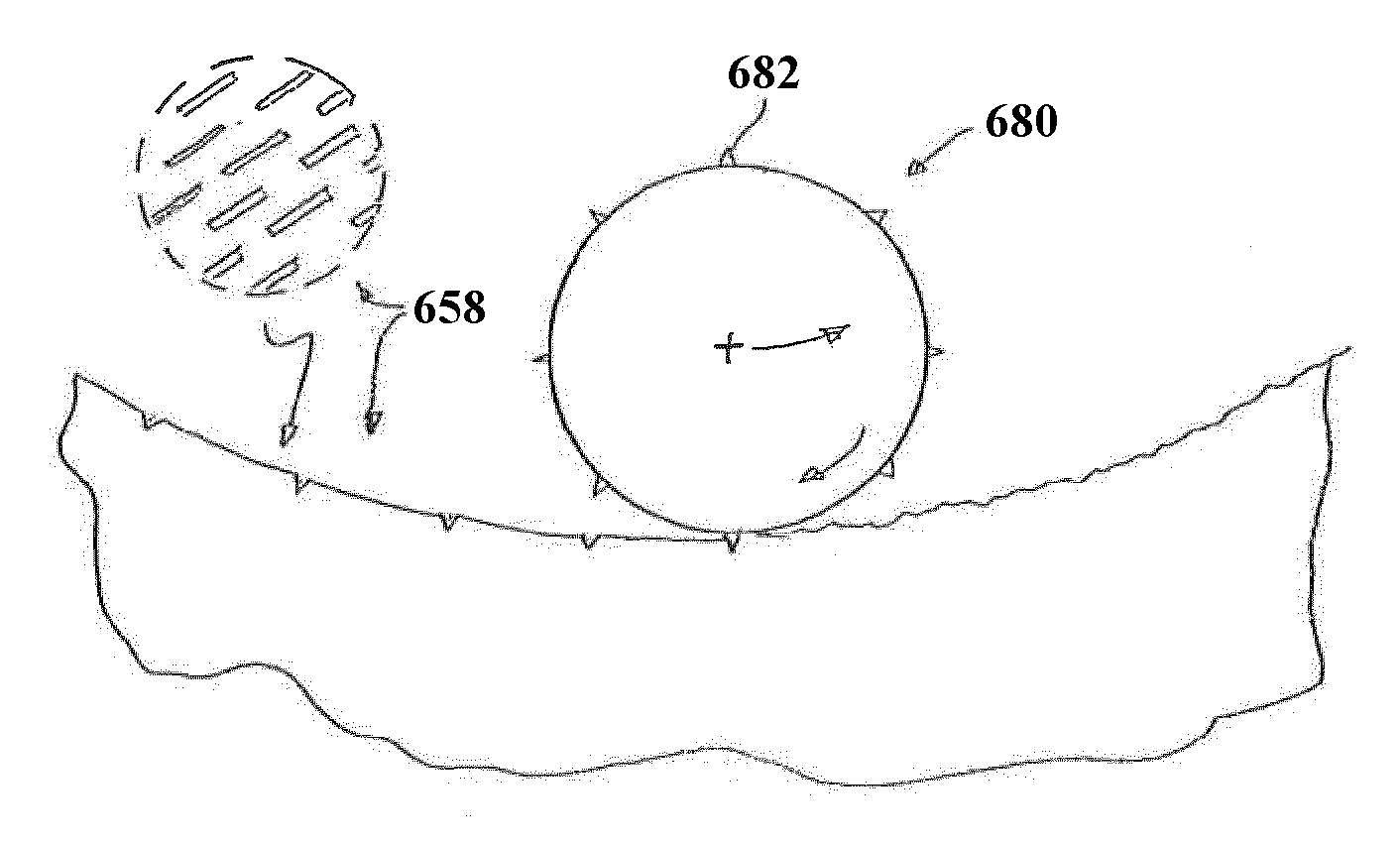
The invention relates to a machining method for machining a curved workpiece surface (210) of a workpiece (200), in which a roll forming operation is carried out. At least one roller element (180A, 180B, 180C) of a machining tool (100) is rolled under a contact pressure against a segment (198) of the curved workpiece to be machined. An outer surface of the roller element comprises a rough surface structure in at least one working segment (190A, 190B, 190C) intended for rolling contact with the workpiece surface. The contact pressure is set so that a rough roll-formed structure is generated when rolling by locally deforming the workpiece material without removing material in the area of the workpiece surface being machined. The machining method can be used, for example, for machining the inner surface of a hole in a workpiece, in particular for roughening the workpiece surface for subsequent coating. The invention further relates to the machining tool and the workpiece thus produced.

Description

technical field [0001] The invention relates to a method according to the preamble of claim 1 for machining a curved workpiece surface, in particular for machining the inner surface of a bore in a workpiece, and a method according to the preamble of claim 9 A machining tool for machining a curved workpiece surface of a workpiece that can be used for carrying out the method. Furthermore, the invention relates to a workpiece obtainable by means of the machining method and / or the machining tool. Background technique [0002] Embodiments of the invention can also be used to produce tribologically demanding, rotationally symmetrical or otherwise curved sliding surfaces on workpieces, preferably for engine production. A particularly preferred field of application lies in the production of cylinder running surfaces in internal combustion engines, that is to say in the machining of the inner surfaces of cylinder bores in engine blocks or in cylinder liners to be installed in engine...

Claims


Application Information

Patent Timeline
Patent Type & Authority Applications(China)
IPC IPC(8): B21H7/18B23B27/24C23C4/02B23P9/02
CPCB21H7/18B23B27/24B23B41/12B23B2215/24B23P9/02B23P9/025C23C4/02C23C4/18C23C30/005B24B39/023B21B15/00
Inventor J.施密德T.维特F-A.哈维尔S.策勒
Owner ELGAN DIAMANTWERKZEUGE
Learn More