Shaving tool

A technology for scraping tools and cutting edges, which is applied in the direction of manufacturing tools, metal processing equipment, metal extrusion cleaning equipment, etc., can solve the problems of complex devices, shortened tool life, and large size, and achieve the effect of reducing unevenness and suppressing vibration

Inactive Publication Date: 2013-12-11
KOBE STEEL LTD
View PDF10 Cites 0 Cited by
  • Summary
  • Abstract
  • Description
  • Claims
  • Application Information

AI Technical Summary

Problems solved by technology

[0010] However, in the scraping method disclosed in Patent Document 1, a forced cooling device that sprays coolant directly to the cutting edge of the die is required, so the device is complicated.
Patent Document 2 mainly discloses the blade edge shape of a scraping die for relatively soft metal wires such as copper and copper alloys from the viewpoint of tool wear, but it is not a structure for steel wire materials harder than copper and copper alloys.
In addition, no consideration is given to the smoothness of the cut surface after shaving
[0011] In the process of cutting and removing the surface layer of the wire rod with the above-mentioned scraping tool, chips may be generated on the edge of the scraping tool due to the influence of residual scale and surface unevenness
When a chip is formed on the edge of the blade, processing flaws (cutting flaws) remain on the surface of the wire rod, and the processing force (cutting force) acting on the edge of the blade increases, so tool wear progresses significantly, and there is a problem that tool life is shortened

Method used


Image

  • Shaving tool
  • Shaving tool
  • Shaving tool

Examples


Embodiment Construction

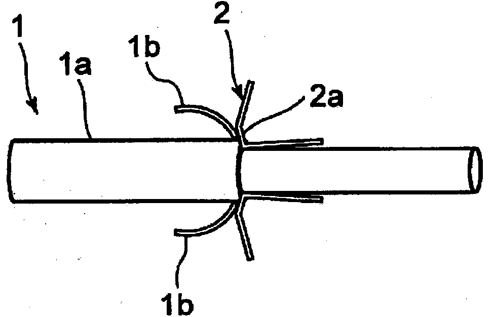
[0032] Below, according to the attached Figure 1 to Figure 7 One embodiment of the present invention will be described.

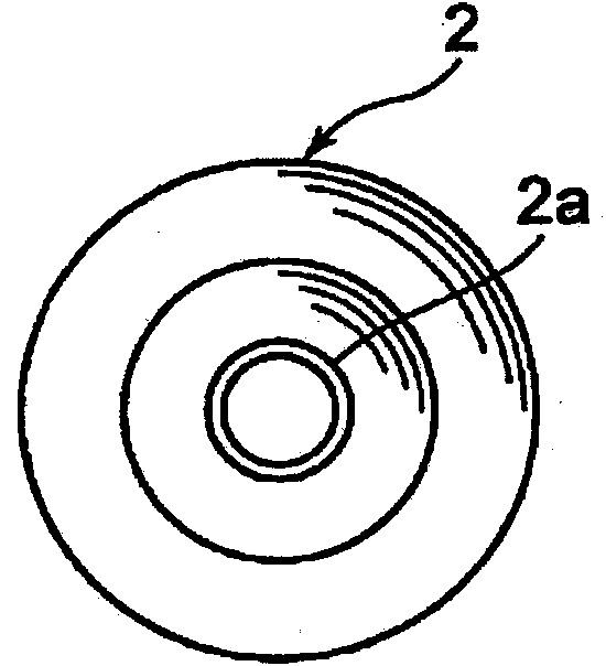
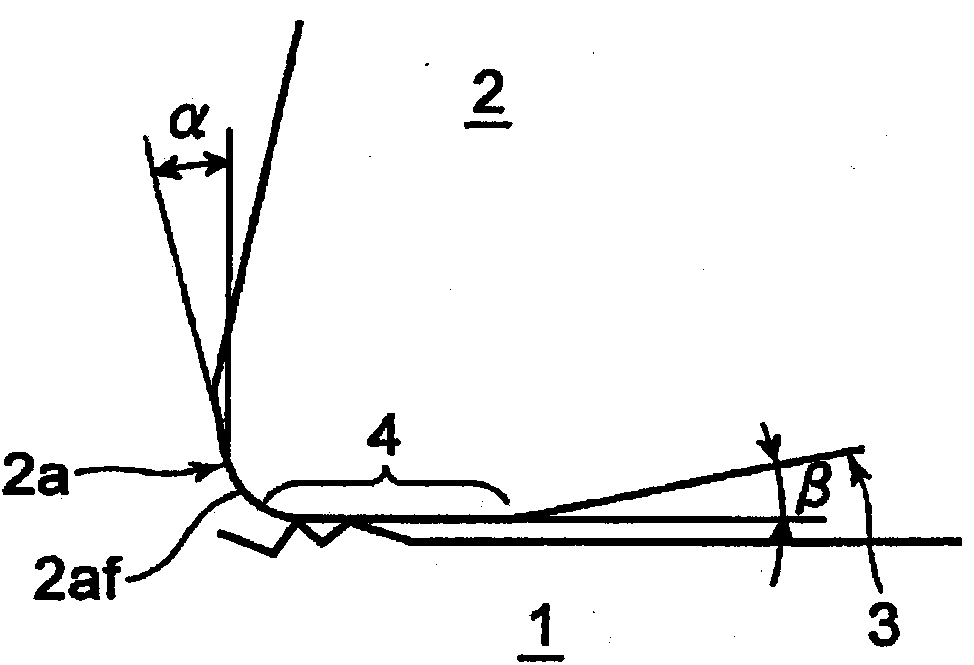
[0033] figure 1 It is an explanatory drawing which schematically shows the shaving process of the wire rod using the shaving tool of one embodiment. The steel wire material (hereinafter referred to as "wire material") 1 as the workpiece is usually arranged on the output side of the scraping tool 2 ( figure 1 under the action of traction generated by the winder (not shown) on the right side of the figure 2 The scraping tool 2 of the shape shown. The surface layer 1a of the wire rod 1 is cut over the entire circumference by the cutting edge 2a. Surface defects of the wire rod 1 are removed together with the chips 1b. Such as image 3 As shown, the cutting edge 2a of the scraping tool 2 for scraping the surface of the wire rod 1 is formed so that the rake angle α becomes a negative value in the range of -5° to -30°. In addition, the cutting edge 2af o...


PUM

PropertyMeasurementUnit
lengthaaaaaaaaaa

Abstract

The invention provides a shaving tool. The rake angle (a) of the cutting blade (2a) of the shaving tool (2) is set to a negative value, such that a flat surface (4) of an appropriate length is formed on the flank (3). Due to the negative rake angle, in an event of misalignment between the centers of the shaving tool (2) and a wire material (1), a cutting force component acts to bring the wire material (1) back to the center of the shaving tool (2). Also, because the roughness on the worked surface of the wire material created by the blade edge is reduced by the flat surface (4), the smoothness is improved to ameliorate the surface quality, and chipping of the blade edge and wearing of the tool can be minimized.

Description

technical field [0001] The present invention relates to a shaving tool for peeling (shaving) the surface of the wire used in the manufacturing process of the wire used for suspension bridge cables, springs, and the like. Background technique [0002] On the surface of the wire rod after the hot rolling process, especially the steel wire rod, there are many irregularities due to defects such as scale and rolling flaws remaining. In order to smooth the surface of such a wire rod and improve the quality of the surface, the surface layer of the wire rod is often removed by cutting off the entire circumference of the wire rod with a die-shaped scraping tool (for example, refer to Patent Documents 1 and 2). [0003] 【Prior technical literature】 [0004] 【Patent Literature】 [0005] [Patent Document 1] Japanese Patent Laid-Open No. 2007-283432 [0006] [Patent Document 2] Japanese Patent Application Laid-Open No. 5-228729 [0007] In the wire scraping method disclosed in Patent...

Claims


Application Information

Patent Timeline
Patent Type & Authority Applications(China)
IPC IPC(8): B23D79/12
CPCB21C43/04Y10T83/929B23D79/12
Inventor 尾崎胜彦加藤史拓正崎保百崎宽
Owner KOBE STEEL LTD
Why Eureka
Try Eureka