Method for fabricating an electrophoretic display device

A technology of electrophoretic display and equipment, applied in the direction of instruments, nonlinear optics, optics, etc., can solve the problems such as difficult to perform micro-unit sealing, difficult to form micro-unit partition walls, etc., to achieve quality text, minimize defect rate, high The effect of quality text

Inactive Publication Date: 2013-12-11
KOLON IND INC
View PDF5 Cites 3 Cited by
  • Summary
  • Abstract
  • Description
  • Claims
  • Application Information

AI Technical Summary

Problems solved by technology

[0012] However, the microcell type electrophoretic display has the following problems: it is difficult to form the partition walls constituting the microcells, and it is difficult to perform the process of filling the charged particle slurry in the microcells and sealing the microcells without voids

Method used


Image

  • Method for fabricating an electrophoretic display device
  • Method for fabricating an electrophoretic display device
  • Method for fabricating an electrophoretic display device

Examples


example 1

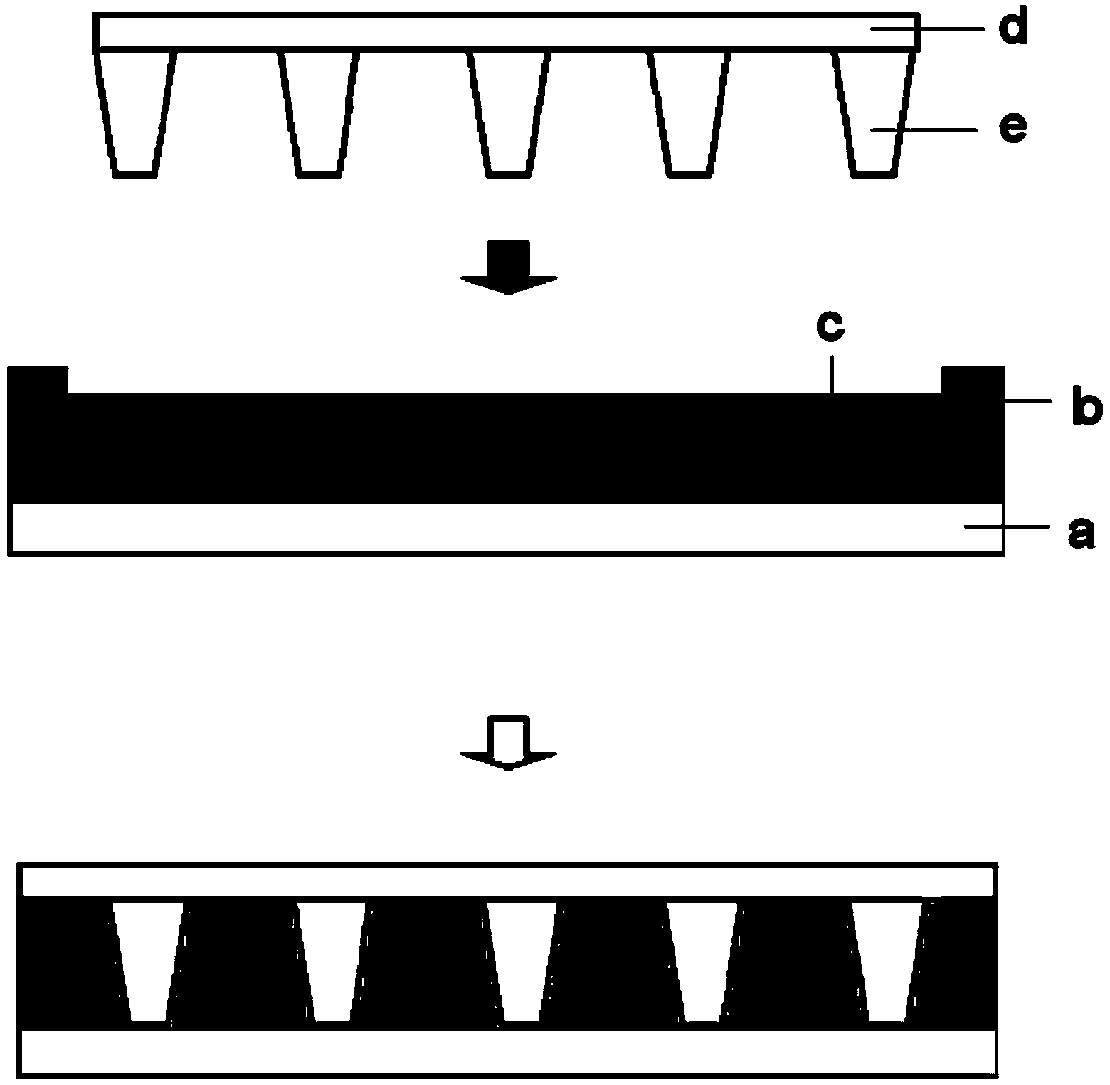
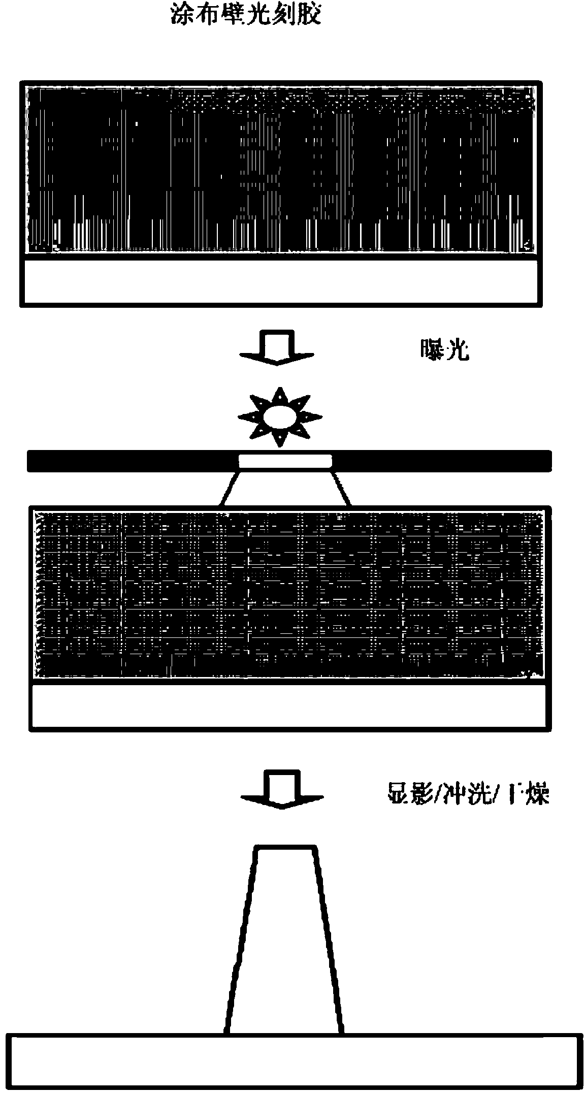
[0133] (1) Forming microcell-shaped partition walls on the first substrate

[0134] Use dry film photoresist ( BU-6200 series, Kolon Industries Co., Ltd.) formed partition walls on ITO / PET film (6 feet long, 5 mm thick).

[0135] More specifically, the dry film photoresist is composed of polyimide, binder resin (ie, cross-linked oligomers, such as urethane acrylate or polyester acrylate), photoinitiator and photopolymerization complex solution of monomers. A dry film resist was coated on the ITO / PET film, followed by exposure, development, and rinse using a square mask (longest diagonal: 50 μm) sequentially to form partition walls.

[0136] For this purpose, the section of the partition wall was trapezoidal (upper base 8 μm, lower base 10 μm) and its height was 30 μm.

[0137] (2) Forming a photocurable resin layer and edges on the second substrate

[0138] Spin-coat on ITO electrodes (6 inches) containing transparent acrylic-based photoresist ( Kolon Industries Co., ...

example 2

[0153] (1) Manufactured in the same manner as described in Example 1, except that in the step of forming microcell-shaped partition walls on the first substrate, the partition walls were formed by exposure, development, and flushing using a square mask Electrophoretic display device.

[0154] (2) Observation of the fabricated electrophoretic display device using a reflective digital microscope (Xi-Cam BV410, Bestecvition Co.Ltd.) shows that the results are the same as in Example 1, that is, each micro-unit is uniformly sealed, and there is no Any gap, and the partition wall and the photocurable resin layer are firmly combined without any separation between the two.

[0155] Figure 5 is a partial view of the observed electrophoretic display device.

example 3

[0157] (1) Manufactured in the same manner as described in Example 1 except that the temperature was maintained at 4°C in the step of combining the first substrate having the partition wall and the second substrate having the photocurable resin layer and edges Electrophoretic display device.

[0158] (2) Observation of the fabricated electrophoretic display device using a reflective digital microscope (Xi-Cam BV410, Bestecvition Co.Ltd.) shows that the results are the same as in Example 1, that is, each micro-unit is uniformly sealed, and there is no Any gap, and the partition wall and the photocurable resin layer are firmly combined without any separation between the two.


PUM

PropertyMeasurementUnit
heightaaaaaaaaaa
thicknessaaaaaaaaaa
heightaaaaaaaaaa

Abstract

The present invention relates to a method for fabricating an electrophoretic display device, which includes: a step of forming partitions on a first substrate; a step of filling a three-dimensional space with a slurry of charged particles, wherein the three-dimensional space is formed by a photo-curable or thermosetting resin layer and a sealing material formed on the resin layer to define the boundary of the three-dimensional space; and a step of coupling the first substrate to the resin layer in order to immerse the partitions in the slurry of charged particles. Accordingly, the defect rate of the final product can be minimized, and an electrophoretic display device can have a high contrast ratio and improved visibility, to thereby represent high-definition text.

Description

technical field [0001] The present invention relates to a method of manufacturing an electrophoretic display device, and more particularly, to a method of manufacturing an electrophoretic display device that minimizes the defect rate of the final product and provides a display with high contrast and enhanced visibility Electrophoretic display device for high quality text. Background technique [0002] Electronic paper or digital paper, also known as electronic paper, is an electronic device that is portable and can be opened at any time like a paper book, newspaper or paper magazine and written on like ordinary paper. [0003] Electronic paper takes the form of an electrophoretic display, which is very advantageous compared to traditional flat displays in that it is bendable, has a much lower production cost, and has far superior energy efficiency, requiring no separate backlight. [0004] This electronic paper has high resolution or clarity and a wide viewing angle, and c...

Claims


Application Information

Patent Timeline
Patent Type & Authority Applications(China)
IPC IPC(8): G02F1/167G02F1/1679
CPCG02F1/1681G02F1/167G02F1/1679
Inventor 明惠珍宋镐石刘贤贞尹泳瑞
Owner KOLON IND INC
Why Eureka
Try Eureka