
Hazelnut huller
A peeling machine and hazelnut technology, applied in the fields of shelling, pod removal, food science, etc., can solve the problems of complicated artificial hazelnut peeling operation, difficult hazelnut peeling quickly, and no hazelnut, so as to reduce the impurity rate and mechanical effect Uniform and reduce breakage effect
- Summary
- Abstract
- Description
- Claims
- Application Information
AI Technical Summary
Problems solved by technology
Method used
Image

Examples
Embodiment Construction
[0022] The present invention will be described in further detail below in conjunction with the accompanying drawings and embodiments.
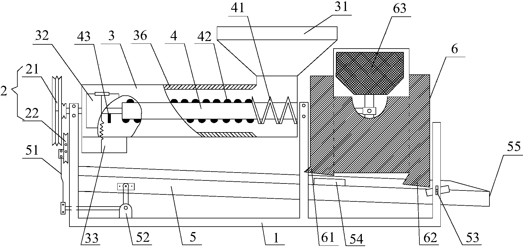
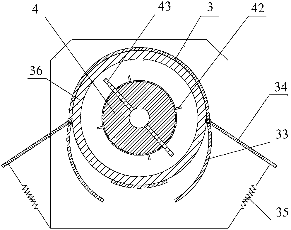
[0023] Such as figure 1 and figure 2 As shown, a hazelnut peeling machine includes a frame 1, a cylindrical body 3, a main shaft 4, a drive mechanism 2, a sieve layer 5 and a fan box 6, and the cylindrical body 3, the drive mechanism 2, the sieve layer 5 and the fan box 6 is installed on the frame 1, and the drive mechanism 2 is connected with the main shaft 4 and the screen layer 5 respectively. The driving mechanism 2 and the fan box 6 are respectively installed at the two ends of the cylindrical body 3. The driving mechanism 2 includes a power unit (not shown), a driving wheel 21 and a driven wheel 22. The power unit is connected to the driving wheel 21, and the driving The wheel 21 is connected with the driven wheel 22 by a belt, the driving wheel 21 is connected with the main shaft 4, and the driven wheel 22 is connected with the sieve...
PUM
 Abstract
Description
Claims
Application Information