Thermal Expansion Forming Method of Stainless Steel Rectangular Cross-section Ring

A technology of rectangular cross-section and ring parts, applied in forming tools, metal processing equipment, manufacturing tools, etc., can solve the problems of high equipment requirements, large energy consumption, low productivity, etc., achieve smooth metal flow, simplify the bulging process, The effect of improving productivity

Active Publication Date: 2016-02-03
GUIZHOU AVIATION TECHN DEV
View PDF3 Cites 0 Cited by
  • Summary
  • Abstract
  • Description
  • Claims
  • Application Information

AI Technical Summary

Problems solved by technology

This method adopts an open bulging method to bulge a rectangular cross-section ring through three consecutive small deformations and two rotations. Each bulging can only be realized by adjusting and controlling a large number of process parameters. The process is cumbersome and the productivity is low. The energy consumption is large, the production preparation time and production cycle are long, and the requirements for equipment are also high. In the actual production process, it is not conducive to controlling product quality and organizing mass production. It is difficult to obtain high-quality, precise, efficient, environmentally friendly and low-cost products. Ring

Method used


Image

  • Thermal Expansion Forming Method of Stainless Steel Rectangular Cross-section Ring
  • Thermal Expansion Forming Method of Stainless Steel Rectangular Cross-section Ring
  • Thermal Expansion Forming Method of Stainless Steel Rectangular Cross-section Ring

Examples


specific Embodiment approach

[0032] The main chemical element content (percentage by weight) of the stainless steel given in the prior art is: C content≤0.1%, Si content≤0.8%, Mn content 17.5%~20.0%, P content≤0.050%, S content ≤ 0.015%, Cr content 17.5% ~ 20.0%, N content ≥ 0.50%, Al content ≤ 0.025%, B content ≤ 0.001%, and the balance being Fe.

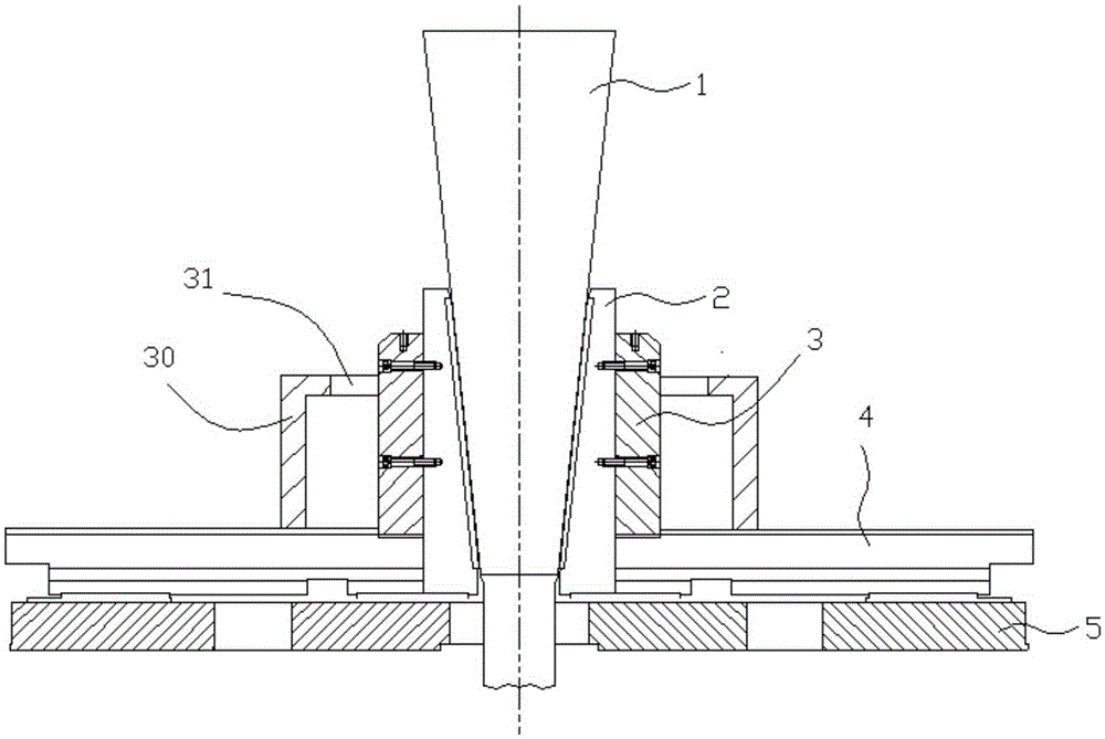
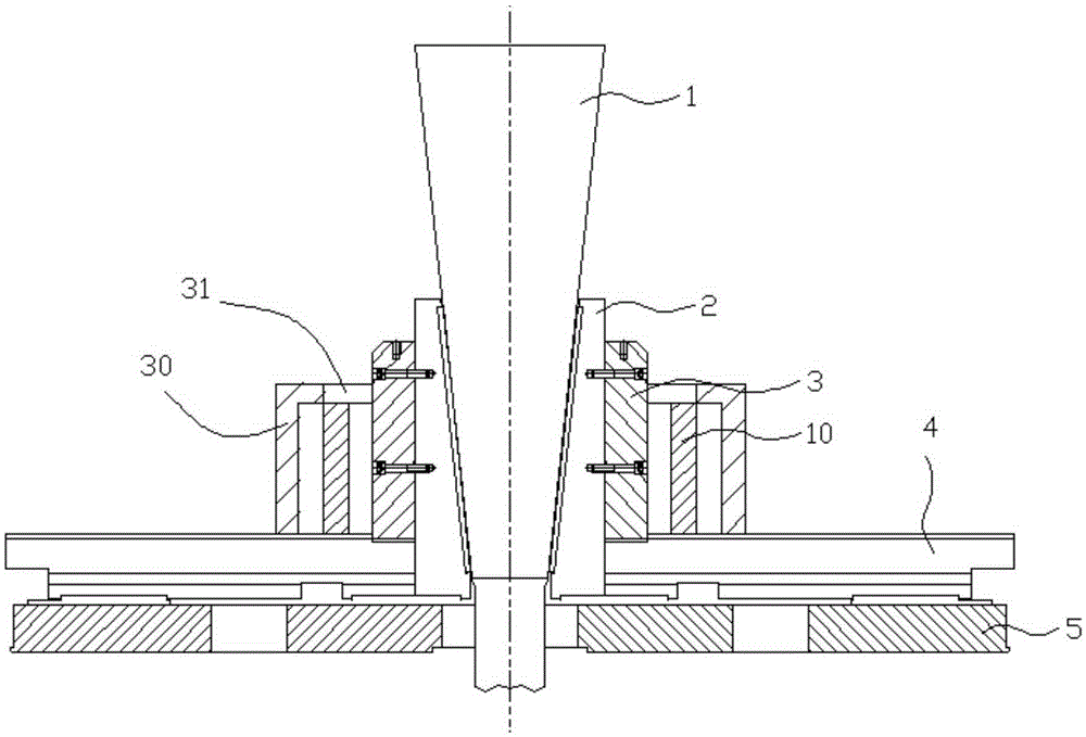
[0033] The structural diagram of the used bulging machine for implementing the thermal bulging method of the present invention given in the prior art is as follows: figure 2 As shown, the bulging machine is mainly composed of a mandrel slider 1, a radial slider 2, a bulging block 3, a workbench 4 and a guide rail 5. The mandrel slider 1 is conical and is set in the radial slider 2 to cooperate with the conical inner peripheral surface of the radial slider 2. The mandrel slider 1 can be driven by the hydraulic cylinder of the bulging machine on the radial slider 2. Move up and down in the axial direction and squeeze the radial slider 2; the radial slider 2 is...


PUM

PropertyMeasurementUnit
thicknessaaaaaaaaaa
heightaaaaaaaaaa

Abstract

The invention discloses a heat bulging forming method for stainless steel rectangular cross section annular elements. The method comprises the following steps that a preheated mold sleeve is fixed on a work table of a bulging machine, then, a heated stainless steel rectangular cross section annular element is sheathed on the periphery of a preheated bulging block in the bulging machine so that the heated stainless steel rectangular cross section annular element is positioned in an annular space surrounded by the outer circumference surface of the bulging block and the inner annular surface of the mold sleeve, the bulging machine is started so that the bulging block extrudes the annular element from the inner circumference surface of the annular element in the radial direction, deforms 10 percent to 13 percent, and is then extruded into the inner annular surface of the mold sleeve, a sealed die cavity surrounded by the outer circumference surface of the bulging block and the inner annular surface of the mold sleeve is fully filled, and the bulged rectangular cross section annular element is formed after the pressure preservation. The method adopts one-step large-deformation-quantity bulging forming, the operation is simplified, and the bulged rectangular cross section annular element with high dimension precision, high product quality and high productivity is obtained. The bulged rectangular cross section annular element is mainly used for rotating body parts of tubular casings and the like used in the fields of aeronautics and astronautics and the like.

Description

technical field [0001] The invention relates to a bulging method for a ring, in particular to a thermal expansion forming method for a stainless steel rectangular section ring. Background technique [0002] In the field of ring forming technology, with the development of aviation, aerospace, shipbuilding, nuclear energy, gas turbines, wind power and other industries, the requirements for high reliability, long life and low cost of ring parts require the forming dimensional accuracy, structure and quality of ring parts. Performance also puts forward higher requirements, and the forming of ring parts is developing in the direction of high quality, precision, high efficiency, environmental protection and low cost. [0003] After the stainless steel rectangular cross-section ring (referring to the ring with a rectangular cross-section in the longitudinal section) is rolled by a ring rolling mill, due to the influence of the rolling process and equipment limitations, its dimensio...

Claims


Application Information

Patent Timeline
Patent Type & Authority Patents(China)
IPC IPC(8): B21D31/04B21D37/10
Inventor 宋捷吴永安陈学洪项春花张园园
Owner GUIZHOU AVIATION TECHN DEV
Why Eureka
Try Eureka