Machining Technology of Rotor Shaft and Its Rotor Shaft

A processing technology and rotor shaft technology, applied in the direction of shafts, bearings, shafts, mechanical equipment, etc., can solve the problems of poor product accuracy consistency, large initial investment, poor production safety, etc., and achieve good product accuracy consistency , quality improvement, production efficiency improvement effect

Inactive Publication Date: 2016-03-02
上海秋乐实业有限公司
View PDF6 Cites 0 Cited by
  • Summary
  • Abstract
  • Description
  • Claims
  • Application Information

AI Technical Summary

Problems solved by technology

It is time-consuming and labor-intensive, and the initial investment is large, and the production safety is poor, the quality is unstable, and the product accuracy consistency is not good

Method used


Image

  • Machining Technology of Rotor Shaft and Its Rotor Shaft
  • Machining Technology of Rotor Shaft and Its Rotor Shaft
  • Machining Technology of Rotor Shaft and Its Rotor Shaft

Examples


Embodiment Construction

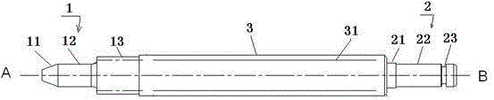
[0033] see figure 1 . Rotor shaft is one of the important parts in mechanical transmission. The rotor shaft includes an A-shaft section 1 for connecting with the motor rotor, a B-shaft section 2 for connecting with the drive shaft, and an intermediate shaft section 3 connected between the A-shaft section and the B-shaft section, The A-shaft segment includes a conical portion 11, a small shaft portion 12, and a gear portion 13 that are sequentially connected, and the B-axis segment includes a sequentially connected blocking portion 21, a shaft portion 22, and a user end formed near the end. The fixing groove 23 for setting the fixing ring.

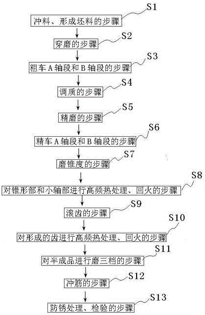
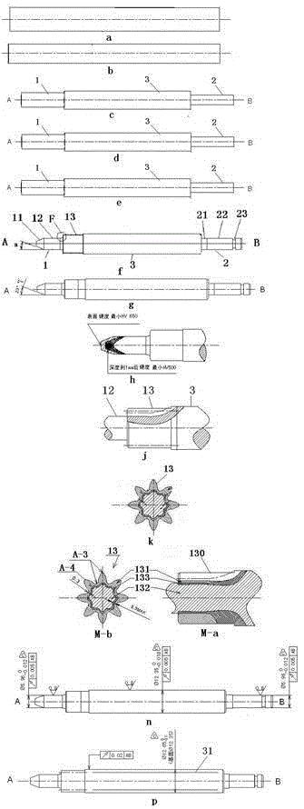
[0034] see figure 2 and image 3 . The rotor shaft machining process of the present invention, the following steps are executed in sequence:

[0035] The step S1 of stamping and forming a blank; punching with a punch to form a blank, such as image 3 middle a;

[0036] Wearing and grinding step S2: Use a centerless grinder to wear ...


PUM

PropertyMeasurementUnit
hardnessaaaaaaaaaa
hardnessaaaaaaaaaa
hardnessaaaaaaaaaa

Abstract

The invention discloses a rotor shaft processing technology, which is characterized in that the following steps are performed in sequence: punching and forming a blank; wearing and grinding: rough turning A shaft section and B shaft section; quenching and tempering; fine grinding; finishing turning A shaft segment and B shaft segment; taper grinding; high-frequency heat treatment and tempering for the tapered part and the small shaft part; gear hobbing; high-frequency heat treatment and tempering for the formed teeth to form a semi-finished product; grinding the semi-finished product to the third gear; Ribbon punching; anti-rust treatment and inspection. The invention also discloses a rotor shaft. The equipment of the invention is mostly automatic operation, the production efficiency is improved, the production safety is good, the quality of the produced rotor shaft is improved, the product accuracy is consistent, the waste products are reduced by more than 60% compared with the original process, and it has the advantages of saving raw materials, reducing production costs, and saving energy. Advantages of energy consumption.

Description

technical field [0001] The invention relates to a rotor shaft processing technology and the rotor shaft. Background technique [0002] Rotor shaft is one of the important parts in mechanical transmission. Due to the high requirements on the rotor shaft and the difficulty in processing, the prior art generally uses manual operations by experienced workers. The process flow is as follows: Use punching machine to punch material → use cylindrical grinder such as MB1320 to wear and grind → use small CNC rough turning → external coordination quality → use cylindrical grinder such as MB1320 to wear and grind → use instrument lathe three-dimensional C0632 fine car to punch AB surface → use Instrument lathe such as C0632 cutting length → use C0632 instrument lathe to turn the outer circle → use C0632 instrument lathe to cut groove and chamfer → use external cylindrical grinder MB1320 to grind and punch ribs → use small CNC turning gear → use gear hobbing machine hobbing → use high f...

Claims


Application Information

Patent Timeline
Patent Type & Authority Patents(China)
IPC IPC(8): B23P15/14F16C3/02
Inventor 邱云飞
Owner 上海秋乐实业有限公司
Why Eureka
Try Eureka