New Machining Technology of Transmission Shaft Sliding Fork

A sliding fork and transmission shaft technology, which is applied in metal processing equipment, manufacturing tools, milling machine equipment, etc., can solve the problem of uneven force on the root of the two lugs of the sliding fork, inconsistent wall thickness difference between the two fork lugs, and excessive initial value of dynamic balance. Poor and other problems, to achieve the effect of reducing equipment requirements, reducing processing area, and accurately positioning benchmarks

Active Publication Date: 2015-12-23
XUCHANG YUANDONG DRIVE SHAFT +1
View PDF5 Cites 2 Cited by
  • Summary
  • Abstract
  • Description
  • Claims
  • Application Information

AI Technical Summary

Problems solved by technology

Due to the separate processing of the spline bottom hole 3 and the end face of the rod part 1 in this processing method, it is necessary to switch the machine tool for two positioning and clamping during the processing process, resulting in the change of the clamping position during the clamping process and the misalignment of the datum
In turn, the axis of the processed spline bottom hole 3 is not perpendicular to the end face of the rod part 1, and the perpendicularity is generally between 0.2-0.5mm, which is poor.
In the subsequent spline drawing process, the end face of the rod part 1 is positioned, and the leading part of the spline broach is designed based on the inner hole. Vertical, may cause spline offset
The subsequent processing is based on the internal spline, so it is easy to cause the wall thickness difference between the two fork ears to be inconsistent in the process of milling the ear holes 4 of the two fork ears 2 (generally, the wall thickness difference is 0.8- between 1mm)
[0004] The above problems will lead to the following results: 1. The splines are pulled out, which makes it difficult to assemble the matching splines
2. The initial value of the dynamic balance is out of tolerance, which seriously affects the product quality
3. When the wall thickness difference between the two ears is too large, it is easy to cause uneven stress on the roots of the two ears of the sliding fork under working conditions, and tearing of the ear hole is prone to occur in places with small wall thicknesses.

Method used


Image

  • New Machining Technology of Transmission Shaft Sliding Fork
  • New Machining Technology of Transmission Shaft Sliding Fork
  • New Machining Technology of Transmission Shaft Sliding Fork

Examples


Embodiment Construction

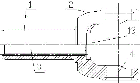
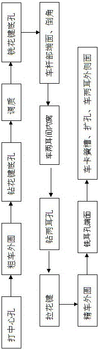
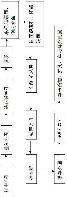
[0037] Such as figure 1 , image 3 , Figure 4 with Figure 5 As shown, the new processing technology of transmission shaft sliding fork of the present invention comprises the following steps:

[0038] (1), punch the center hole of the rod end face of the sliding fork;

[0039] (2) Based on the center hole, the outer circle of the rod part 1 is roughly turned;

[0040] (3) Based on the outer circle of the rod part 1 of the sliding fork, drill the spline bottom hole 3;

[0041] (4) Refining and tempering the entire sliding fork;

[0042] (5) Based on the outer circle of the rod part 1, the end face of the rod part 1 of the sliding fork is chamfered with inner and outer corners;

[0043] (6) Based on the outer circle of the rod part 1, use a compound tool to mill the spline bottom hole 3 first, and then process the end face of the rod part 1;

[0044] (7) Based on the outer circle of the rod part 1, the inner socket 13 between the ear parts 2 of the two forks of the car; ...


PUM


Abstract

The invention relates to a new process for processing a sliding fork of a transmission shaft. The new process comprises the following steps: (1) punching a central hole in the end face of a rod part of the sliding fork; (2) roughly turning the excircle of the rod part by taking the central hole as a benchmark; (3) drilling a spline bottom hole by taking the excircle of the rod part as a benchmark; (4) performing tempering treatment on the whole sliding fork; (5) turning the end face of the rod part of the sliding fork and chamfering inner and outer angles by taking the excircle of the rod part as a benchmark; (6) milling the spline bottom hole by using a composite cutter and processing the end face of the rod part by taking the excircle of the rod part as a benchmark; (7) turning an inner nest between two fork lug parts; (8) drilling two lug holes; (9) pulling a spline; (10) finely turning the excircle of the rod part of the sliding fork; (11) milling the end faces of the two lug holes; and (12) turning a jump spring groove, reaming and turning the outer sides of the two fork lug parts. By the new process, the product quality of the sliding fork is guaranteed, the rejection rate of the sliding fork is greatly reduced, and the product efficiency is improved.

Description

technical field [0001] The invention belongs to the technical field of machining, and in particular relates to a new process for machining a sliding fork of a transmission shaft. Background technique [0002] With the rapid development of my country's automobile industry, the auto parts manufacturing industry has been brought into the fast lane of rapid development. With the increasing maturity of its processing and manufacturing technology and the advancement of mechanical equipment technology, coupled with the application of a large number of numerical control equipment and the progress of specialized mass production, the competition in the field of auto parts processing has become more and more fierce, and it has entered the era of meager profits. At the same time, coupled with the increasing demand for price cuts from end customers and the cost transfer of main engine manufacturers, auto parts processing companies are forced to continue to innovate and improve, and aband...

Claims


Application Information

Patent Timeline
Patent Type & Authority Patents(China)
IPC IPC(8): B23P15/14B23C5/00
Inventor 张志斌王文陈云升雷务然付浩峰周建喜马喜岭张鹏超尚国生李红俊韩利李建勋曹善江侯光辉王建国唐记敏柴二帅张俊华郭要闯李磊齐瑞晓姚晋业刘金檑赵贺尚向辉
Owner XUCHANG YUANDONG DRIVE SHAFT
Why Eureka
Try Eureka