Vertical conveying device of substrate

A technology for vertically conveying substrates, applied to glass cutting devices, conveyor objects, transportation and packaging, etc., which can solve problems such as picking offsets, inability to obtain high-dimensional precision unit substrates, and substrate cracking

Inactive Publication Date: 2013-12-18
MITSUBOSHI DIAMOND IND CO LTD
View PDF6 Cites 12 Cited by
  • Summary
  • Abstract
  • Description
  • Claims
  • Application Information

AI Technical Summary

Problems solved by technology

Specifically, the small difference in height and rotation speed of each conveyor belt will cause the position of the substrate 1 to deviate.
[0008] Once it is picked up on the pick-up step transfer part C in a state where the position has been shifted, there is the following problem: after marking by advancing or retreating the tool of the marking head installed in the marking unit 30, it cannot Obtain unit substrates with desired high dimensional accuracy
In addition, there are also problems such as pick-up deviation and substrate cracking during the scribing operation.

Method used


Image

  • Vertical conveying device of substrate
  • Vertical conveying device of substrate
  • Vertical conveying device of substrate

Examples


Embodiment Construction

[0035] In order to further explain the technical means and effects of the present invention to achieve the intended purpose of the invention, the specific implementation, structure and features of a vertical substrate transport device proposed according to the present invention will be described below in conjunction with the accompanying drawings and preferred embodiments. And its effect, detailed description is as follows.

[0036] Hereinafter, preferred embodiments of the present invention will be described in more detail with reference to the accompanying drawings. In the embodiments of the present invention, descriptions of constituent elements that are the same as or similar to those of the conventional art will be omitted by using the same reference numerals.

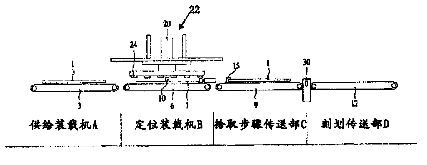
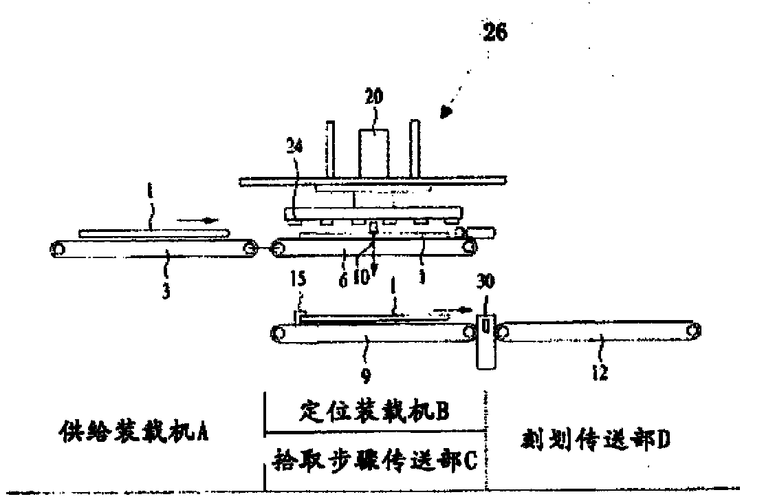
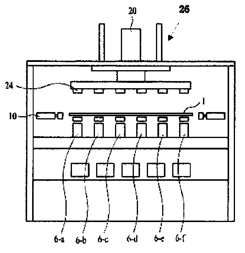
[0037] The vertical transfer device of the substrate of the present invention, such as figure 2 As shown, a supply loader A for supplying a substrate 1 made of a brittle material or the like is installed in a ho...


PUM


Abstract

The invention discloses a vertical conveying device of a substrate capable of preventing the displacement of the substrate from the positioning part to the pick-up part during the weight shifting. The vertical conveying device is provided with a supporting member, a positioning loading machine used to adjusting a positioning part loaded on the substrate of the supporting member, and an absorbing elevating unit capable of absorbing and elevate the substrate of the supporting member, and a pick-up step transmitting part capable of conveying the substrate to the etching unit under the pick-up state of the pick-up member. With the help of the falling operation of the absorbing elevating unit, the weight shifting of the substrate from the positioning loading machine to the pick-up transmitting part can be finished.

Description

technical field [0001] The present invention relates to a vertical substrate transfer device, and more particularly to a substrate vertical transfer device capable of vertically moving a substrate made of a brittle material or the like to a chucking step in a correctly positioned state. Background technique [0002] exist figure 1 , indicates that in the prior art, a substrate that has been put into a loader is transported to a scribing and transporting section where a scribing step is performed. Such as figure 1 As shown, in order to scribe the substrate 1 put into the loader A according to the application, the substrate 1 must be transported horizontally to the scribing unit 30 on the scribing transfer unit D. As shown in FIG. [0003] Therefore, first, the conveyor belt 3 of the supply loader A is rotated, and the board|substrate 1 is conveyed to the positioning loader B. As shown in FIG. The loader B is positioned to perform the work of positioning the X-axis and Y-ax...

Claims


Application Information

Patent Timeline
Patent Type & Authority Applications(China)
IPC IPC(8): B65G49/06B65G47/90B65G47/52
CPCB26D3/085B65G49/06C03B33/03C03B33/037C03B33/10C03B35/163Y02P40/57
Inventor 西尾仁孝
Owner MITSUBOSHI DIAMOND IND CO LTD
Why Eureka
Try Eureka