Vertical shaft shield tunneling machine

A shield machine and shaft technology, which is applied in shaft equipment, sinking, mining equipment, etc., can solve the problems of low shaft construction efficiency and achieve the effects of improving support efficiency, high excavation efficiency, and fast excavation speed

Active Publication Date: 2013-12-18
CHINA RAILWAY ENGINEERING EQUIPMENT GROUP CO LTD
View PDF4 Cites 18 Cited by
  • Summary
  • Abstract
  • Description
  • Claims
  • Application Information

AI Technical Summary

Problems solved by technology

[0003] The purpose of the present invention is to provide a shaft shield mach

Method used


Image

  • Vertical shaft shield tunneling machine
  • Vertical shaft shield tunneling machine

Examples


Embodiment Construction

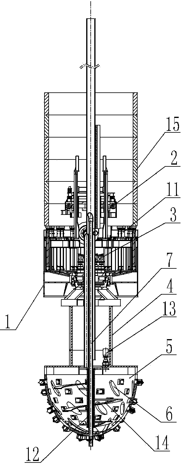
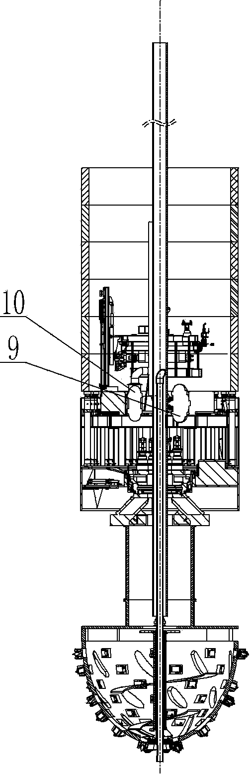
[0016] An embodiment of a shaft shield machine, in figure 1 and figure 2 Among them, the shield body 1 is a cylindrical shield body, and a segment assembly machine 2 is arranged at the rear of the shield body 1. The segment assembly machine 2 here is a segment assembly machine in the prior art, and its structure is similar to that of The working mode is the same as the segment assembly machine of the subway tunnel shield machine in the prior art, and will not be described in detail here. A cutter head drive system 3 is provided inside the shield body 1. The cutter head drive system 3 here is a gear drive system, which has a drive gear driven by a hydraulic motor. The hydraulic motor is fixed on the shield body 1, and the drive gear and the ring gear Engaging transmission, the ring gear is fixed together with the rear portion of the connecting cylinder 4. The connecting cylinder 4 is arranged on the shield body 1 through the slewing support of the main bearing, so that the h...


PUM


Abstract

The invention discloses a vertical shaft shield tunneling machine. A cutter head driving system is arranged in a shield body of the vertical shaft shield tunneling machine; the rotation output end of the cutter head driving system is fixedly provided with a connection barrel extending to the front end; the front end of the connection barrel is fixedly provided with a cutter head with a closed cavity inside; the connection barrel is rotationally supported on the shield body by a main bearing; a stirring device is arranged in the cavity of the cutter head; a cutter is arranged on the outer surface of the cutter head; a slag inlet for communicating the cavity of the cutter head and the outside is reserved on the cutter head; a girder is arranged in the shield body; a slurry input pipeline and a slagging pipeline are arranged in the girder; the front end of the slurry input pipeline extends to the front end face of the cutter head; the rear end part of the cutter head is provided with the slagging pipeline communicated with the cavity of the cutter head; the rear end of the slagging pipeline extends out of the girder; the rear end of the shield body is provided with a propelling system; a thrust oil cylinder of the propelling system is used for being pressed against a duct piece assembled by a duct piece splicing machine. According to the invention, full- face integral forming of a vertical shaft can be implemented and the tunneling speed of the vertical shaft is greatly improved.

Description

technical field [0001] The invention relates to a mechanical device for shaft operations, in particular to a shaft shield machine. Background technique [0002] When excavating underground mineral deposits, it is necessary to form shafts in the excavated strata. With the development of the national economy, there is an increasing demand for underground mineral deposits. The mining of underground mineral deposits has also changed from open-pit mining to underground mining, and the construction of shafts is also rapidly increase, but the shaft digging device does not improve along with the growth of the shaft construction project, and the shaft digging device in the prior art is still relatively backward. The current shafts are generally excavated manually from top to bottom. When a certain depth is reached, the walls are built from the bottom up. The excavation and wall building are carried out alternately. Sometimes it is necessary to spray grout on the well wall before ...

Claims


Application Information

Patent Timeline
IPC IPC(8): E21D1/08
Inventor 李建斌王锴乔文俊
Owner CHINA RAILWAY ENGINEERING EQUIPMENT GROUP CO LTD
Why Eureka
Try Eureka