Demagnetizing method of high-strength steel narrow-gap welding groove

A welding groove and narrow gap technology, applied in welding equipment, magnetic objects, arc welding equipment, etc., can solve the problem of high control requirements, adverse effects of weld penetration and weld formation, and low current density at the center of the weld and other problems, to achieve the effect of strong engineering adaptability, improved demagnetization effect, and low implementation cost

Active Publication Date: 2013-12-18
JIANGSU UNIV OF SCI & TECH
View PDF4 Cites 9 Cited by
  • Summary
  • Abstract
  • Description
  • Claims
  • Application Information

AI Technical Summary

Problems solved by technology

If the longitudinal magnetic field strength is too small, the effect of counteracting the residual magnetism will not be good; if the longitudinal magnetic field strength is too large, the current density at the center of the weld will be too small, which will eventually have an adverse effect on the weld penetration and weld shape
This method offsets the influence of residual magnetism on the arc by applying an external longitudinal magnetic field, but does not fundamentally eliminate the residual magnetism of the groove. At the same time, the control requirements for the intensity of the external longitudinal magnetic field are also very high, and the engineering practicability is poor.

Method used


Image

  • Demagnetizing method of high-strength steel narrow-gap welding groove
  • Demagnetizing method of high-strength steel narrow-gap welding groove
  • Demagnetizing method of high-strength steel narrow-gap welding groove

Examples


Embodiment Construction

[0025] The implementation and implementation process of the present invention will be described in detail below in conjunction with the accompanying drawings, but the scope of protection of the present invention is not limited to the following examples. Before welding, the invention reduces the residual magnetism of the groove through specific point solid welding and the installation of an arc striker, and then uses a pulse demagnetizer to demagnetize the single U or double U-shaped groove several times according to different processes, and replaces it after each demagnetization The demagnetizer coil box moves in the direction until the residual magnetism of the groove drops below a certain value, and the demagnetization operation ends. details as follows:

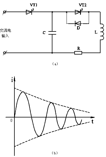
[0026] figure 1 Indicates the basic circuit principle of the pulse demagnetizer, where figure 1 (a) for the pulse demagnetizer RLC Oscillating circuit principle, figure 1 (b) is the oscillating current i decay curv...


PUM


Abstract

The invention discloses a demagnetizing method of a high-strength steel narrow-gap welding groove. The groove residual magnetism is reduced by carrying out the technology of tack welding and run-on plate adding before welding, multiple demagnetizing operations can be carried out on a single U-shaped or double U-shaped groove by a pulse demagnetizing device according to different technologies, a moving direction of a demagnetizing device coil box can be changed after each demagnetizing operation, and the demagnetizing operations can be finished until the groove residual magnetism is reduced to a certain value. By adopting the pulse demagnetizing method and combining the demagnetizing technology of pack welding and run-on plate adding before welding, the demagnetizing effect of a large-size workpiece can be effectively increased, the portability of the demagnetizing device is good, the motion matching of the workpiece is not needed during application, the demagnetizing method is particularly suitable for carrying out the demagnetizing operation in a production field, and the engineering adaptability is strong.

Description

technical field [0001] The invention relates to the field of welding technology, in particular to a pre-weld demagnetization method for narrow-gap welding grooves of high-strength steel. Background technique [0002] Narrow gap metal arc welding can be divided into narrow gap submerged arc welding and narrow gap metal arc welding. It is a single (or double) multi-layer welding process using U-shaped or I-shaped grooves. , suitable for automatic welding of large thickness workpieces. For high-strength alloy steel base materials, due to their high content of alloying elements such as Ni and Cr, they are easily magnetized during rolling forming, storage and transportation, and welding groove processing. When welding this kind of high-strength steel with narrow gap technology, due to the narrow groove gap (generally only a few millimeters or more than ten millimeters), it often leads to a strong residual magnetic field between the two side walls of the groove, thereby destroyin...

Claims


Application Information

Patent Timeline
IPC IPC(8): H01F13/00B23K9/235
Inventor 王加友朱小宇黄平朱杰杨峰
Owner JIANGSU UNIV OF SCI & TECH
Why Eureka
Try Eureka