
Special-shaped radiating element circular polarization planar antenna

A flat-panel antenna and radiating unit technology, applied in the field of satellite communications, can solve problems such as inability to meet, and achieve the effects of increasing efficiency, improving gain, and saving processing and manufacturing costs

Inactive Publication Date: 2013-12-18
SHANDONG GUOWEI SATELLITE COMM
View PDF4 Cites 3 Cited by
  • Summary
  • Abstract
  • Description
  • Claims
  • Application Information

AI Technical Summary

Problems solved by technology

With the increase of satellite communication channel capacity and the congestion of C and Ku frequency band services, L, C, X, Ku and other frequency bands cannot meet the application requirements of high-speed, broadband, and small-caliber terminals.

Method used


Image

  • Special-shaped radiating element circular polarization planar antenna
  • Special-shaped radiating element circular polarization planar antenna
  • Special-shaped radiating element circular polarization planar antenna

Examples


Embodiment 1

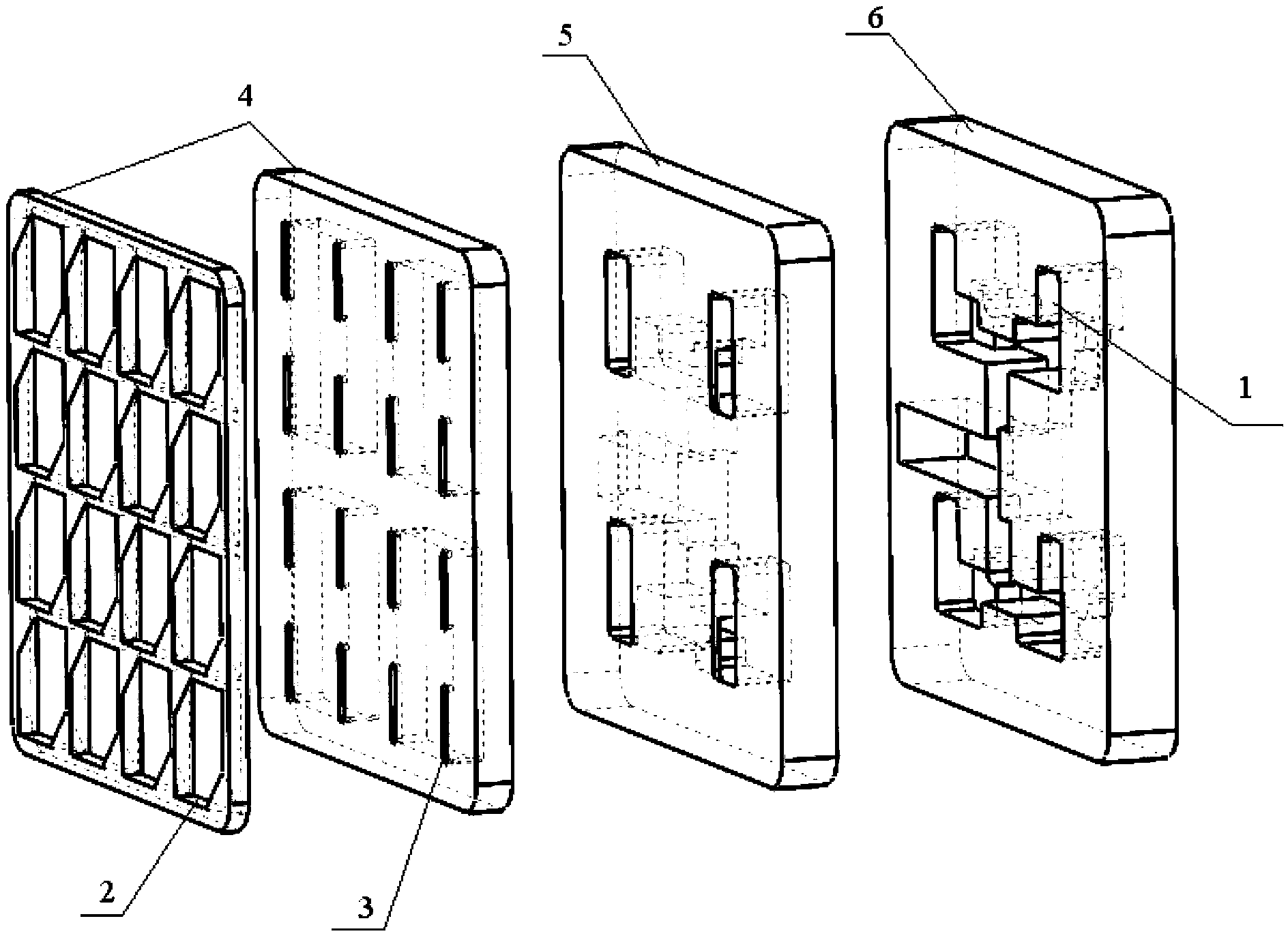
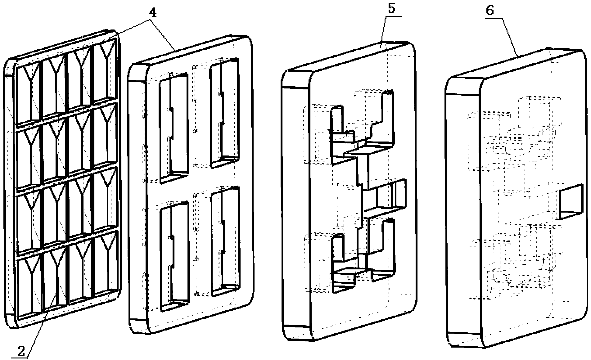
[0024] Such as Figure 1-10 shown.

[0025] A circularly polarized planar antenna with a special-shaped radiating element, comprising a radiating layer 4, a coupling layer 5 and a feeding network 6, and 16 radiators are arranged on the radiating layer 4, and the 16 radiators are arranged in 4 rows× 4 columns are arranged on the radiation layer 4, characterized in that each of the radiators is a special-shaped radiator: one side along the radiation direction is a groove 2 of a square column structure with cut corners, wherein One radiation slit 3 is provided on the side opposite to the coupling layer 5, and the radiation slit 3 is arranged through the groove 2 of the chamfered square column structure;

[0026] The dimensions of the groove 2 of the chamfered square column structure: the depth h is 0.2λ, the length a is 0.4λ, and the width b is 0.3λ, where λ is the operating frequency of the circularly polarized flat panel antenna of the special-shaped radiation unit propagating...

Embodiment 2

[0030] A circularly polarized panel antenna with a special-shaped radiating element as described in Embodiment 1, the difference is that the dimensions of the groove 2 of the chamfered square column structure: the depth h is 0.18λ, the length a is 0.3λ, and the width b is 0.2λ, where λ is the wavelength at which the operating frequency of the patch-loaded circularly polarized panel antenna propagates in the air.

[0031] The size range of the radiation slit 3 is: the length is 0.55λ, and the width is 0.1λ.

Embodiment 3

[0033] A circularly polarized panel antenna with a special-shaped radiating element as described in Embodiment 1, the difference is that the dimensions of the groove 2 of the chamfered square column structure: the depth h is 0.22λ, the length a is 0.5λ, and the width b is 0.4λ, where λ is the wavelength at which the operating frequency of the patch-loaded circularly polarized panel antenna propagates in the air.


PUM

PropertyMeasurementUnit
Width baaaaaaaaaa

Abstract

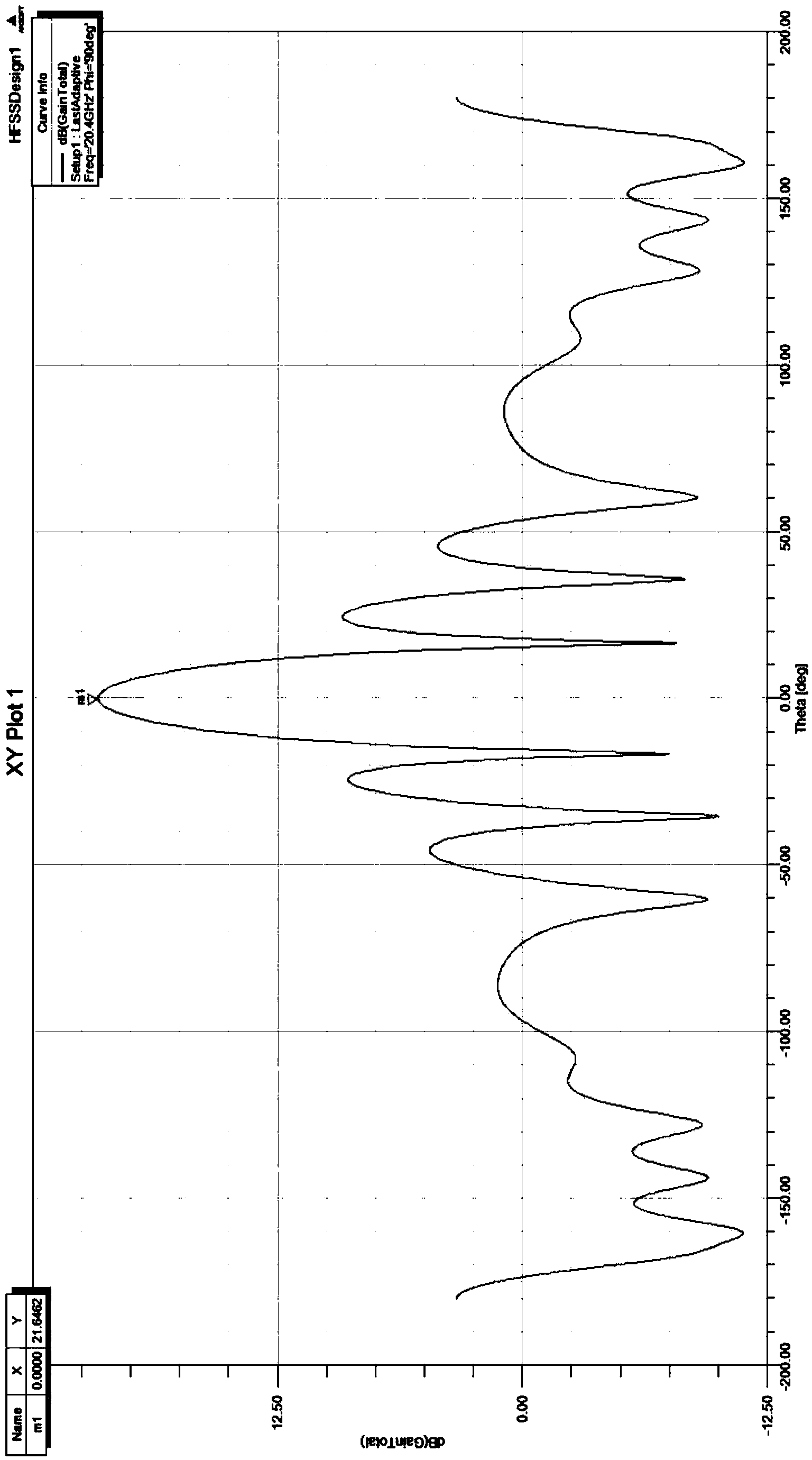
The invention relates to a special-shaped radiating element circular polarization planar antenna which comprises a radiating layer, a coupling layer and a feed network, wherein 16 radiators are arranged on the radiating layer and are arranged in four rows and four lines. The special-shaped radiating element circular polarization planar antenna is characterized in that each radiator is a special-shaped radiator, wherein a groove of a chamfered square column structure is formed in one side of the radiator in the radiation direction; a radiating slot is formed in the side, opposite to the coupling layer, of the radiator; the radiating slot is communicated with the groove of the chamfered square column structure; the feed network is a feed network for a linear polarization planar antenna. By improving the structures of the radiators of the radiating layer, the gain of the special-shaped radiating element circular polarization planar antenna is greatly improved, the efficiency is also improved greatly, and signal quality is substantially improved; the overall physical dimension of the planar antenna is not changed, therefore, the processing and manufacturing cost of the planar antenna is effectively lowered, and after-sale installation and usage are facilitated.

Description

technical field [0001] The invention relates to a circularly polarized panel antenna with a special-shaped radiation unit, belonging to the technical field of satellite communication. Background technique [0002] Satellite communication has the advantages of large coverage, large communication capacity, high transmission quality, convenient and rapid networking, and easy global seamless link. With the increase of satellite communication channel capacity and the congestion of C and Ku frequency band services, L, C, X, Ku and other frequency bands cannot meet the application requirements of high-speed, broadband, and small-caliber terminals. There is an increasing need for satellite communication systems that work in higher frequency bands, have larger bandwidths and higher spectral efficiency. Ka-band satellite communication has become an inevitable trend of future satellite communication due to its advantages of large available bandwidth, large communication capacity, narr...

Claims


Application Information

Patent Timeline
IPC IPC(8): H01Q1/36H01Q13/10H01Q21/24
Inventor 薛丽丽吴超黄朋杨猛
Owner SHANDONG GUOWEI SATELLITE COMM
Learn More