
Driving motor for electric car

A technology for driving motors and electric vehicles, which is applied to electric vehicles, motors, electric components, etc., can solve the problems of complex structure of power units, not suitable for application, and bulky, and achieves simple structure, good overall compactness, and convenient installation. Effect

Inactive Publication Date: 2013-12-18
TAIZHOU LIMA ELECTRIC VEHICLE SCI & TECH
View PDF6 Cites 14 Cited by
  • Summary
  • Abstract
  • Description
  • Claims
  • Application Information

AI Technical Summary

Problems solved by technology

[0003] This kind of power unit has a complex structure and a large volume, so it is not suitable for electric vehicles and other vehicles that require high power unit volume.

Method used


Image

  • Driving motor for electric car
  • Driving motor for electric car
  • Driving motor for electric car

Examples


Embodiment Construction

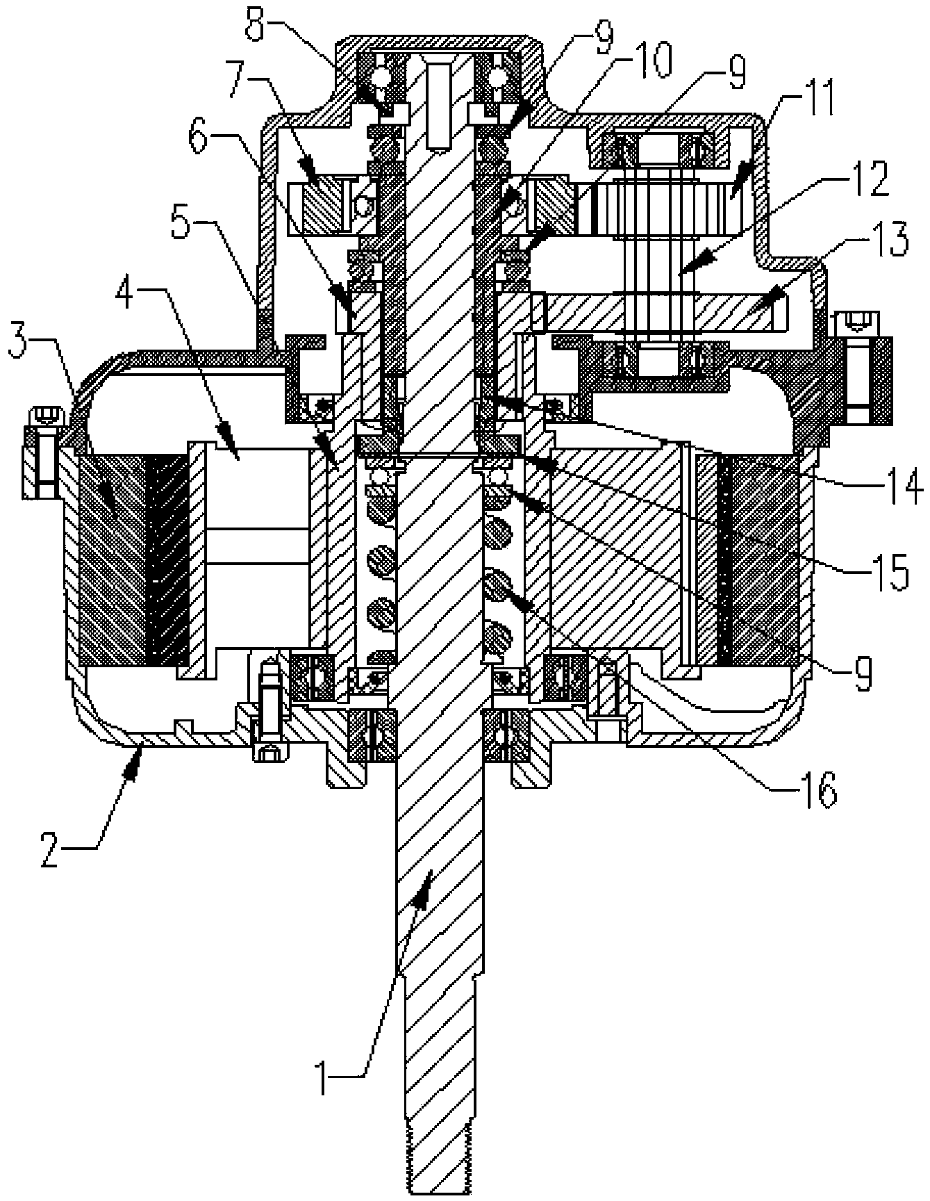
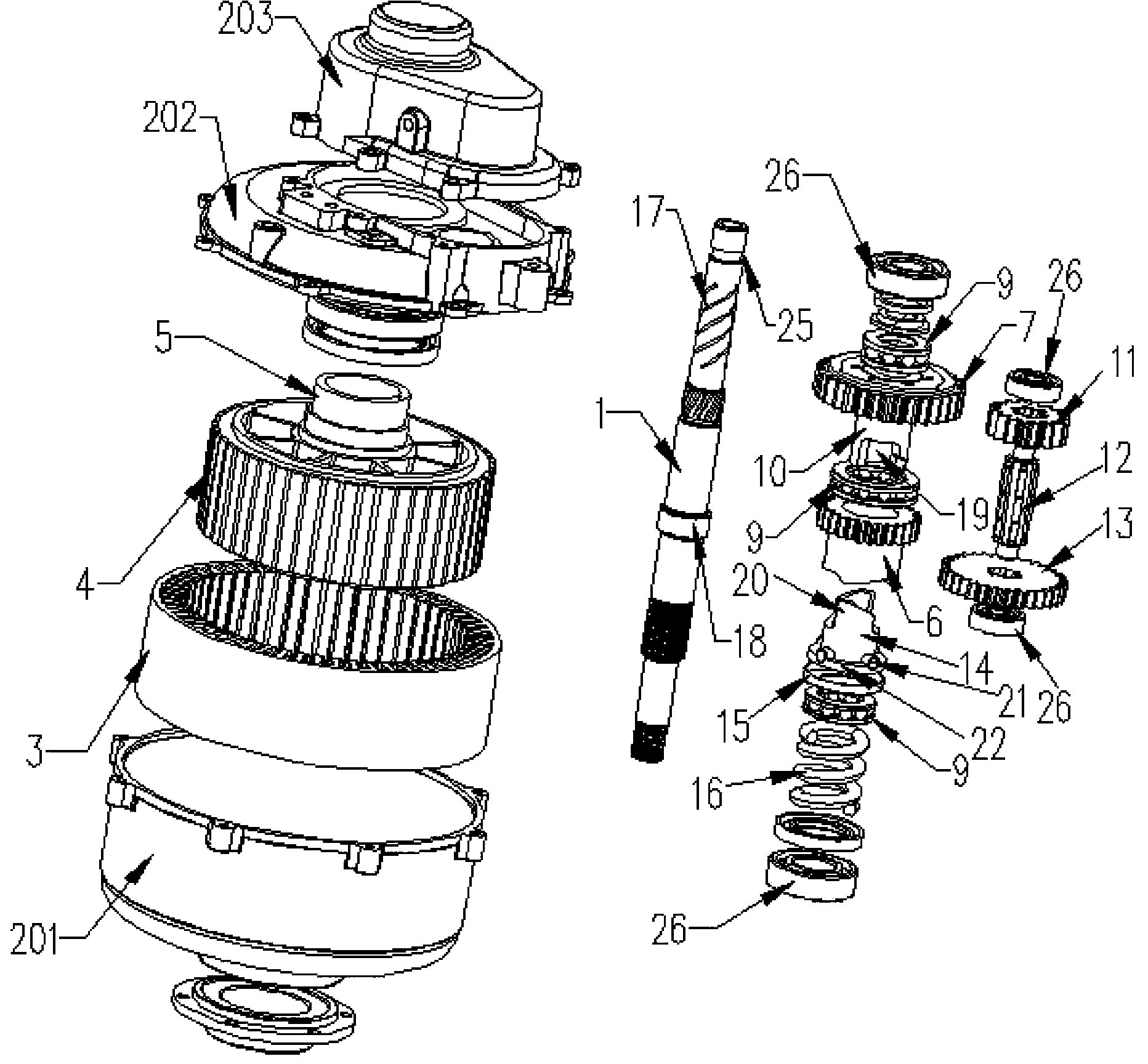
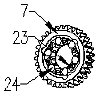
[0026] See figure 1 , 2 , the structure of the electric vehicle transmission motor of the present invention includes a housing 2, the housing 2 is a split structure, which is composed of a plurality of three single structures adapted to the assembly requirements of internal parts, and these three single structures are connected by bolts. And achieve fixation. The casing 2 is provided with a stator 3 and a rotor 4 arranged coaxially, and the main shaft 1 passes through the rotor 4 and can realize power transmission with the rotor 4 .

[0027] A spring 16 and a cylindrical clutch bracket 14 are sleeved on the outer periphery of the main shaft 1 in the housing 2. One end of the spring 16 presses against the boss 18 formed on the main shaft 1, and the other end of the spring 16 acts on the clutch bracket. 14 at one end. The clutch bracket 14 is circumferentially fixed to the main shaft 1 , and a spline structure cooperating with each other is provided between the clutch bracket...


PUM


Abstract

The invention discloses a driving motor for an electric car. The driving motor solves the problem that an existing car power mechanism is complex in structure and inconveniently applied to a car. The technical measures are that the driving motor for the electric car comprises a rotor and a stator, the stator and the rotor are coaxially arranged, and a spindle penetrates through the rotor in a gapped mode. The driving motor for the electric car is characterized in that a clutch support circumferentially and fixedly sleeves the spindle, a spring sleeving the spindle acts on one end of the clutch support, a clutch structure is arranged between the clutch support and the rotor, the clutch structure is connected with a speed reducing mechanism, an inner ring cam sleeving the spindle is connected with the clutch support, and a unidirectional structure is positioned between the inner ring cam and the speed reducing mechanism.

Description

technical field [0001] The invention relates to a transmission motor, in particular to a transmission motor applied to an electric vehicle. Background technique [0002] Chinese invention patent application (application number: 201110285122.6) discloses a power unit for a vehicle. The structure of the power unit for a vehicle is to disconnect the transmission of the rotational power from the primary reduction gear mechanism to the first and second main shafts, The connected first and second clutches are respectively arranged at one end of the first and second main shafts, and the gear trains of a plurality of shift stages selectively established are provided between the first and second main shafts and the countershaft. The vehicle With the power unit, it is possible to have a simple structure with a reduced number of parts and avoid enlargement. The primary reduction gear mechanism includes: a drive gear provided on the crankshaft; a first driven gear that is relatively ro...

Claims


Application Information

Patent Timeline
Patent Type & Authority Applications(China)
IPC IPC(8): H02K7/10F16D41/064F16H1/22
CPCY02T10/64
Inventor 梁振营王平聂文林
Owner TAIZHOU LIMA ELECTRIC VEHICLE SCI & TECH
Learn More