
A valve

A valve, part of the technology, applied in the direction of valve detail, valve device, valve operation/release device, etc., can solve problems such as shortening the service life of the filter

Active Publication Date: 2013-12-18
PARKER HANNIFIN MFG LTD
View PDF6 Cites 4 Cited by
  • Summary
  • Abstract
  • Description
  • Claims
  • Application Information

AI Technical Summary

Problems solved by technology

Sedimentation or grooves shorten filter life as treated water bypasses the portion of the filter media that is not exhausted

Method used


Image

  • A valve
  • A valve
  • A valve

Examples


Embodiment Construction

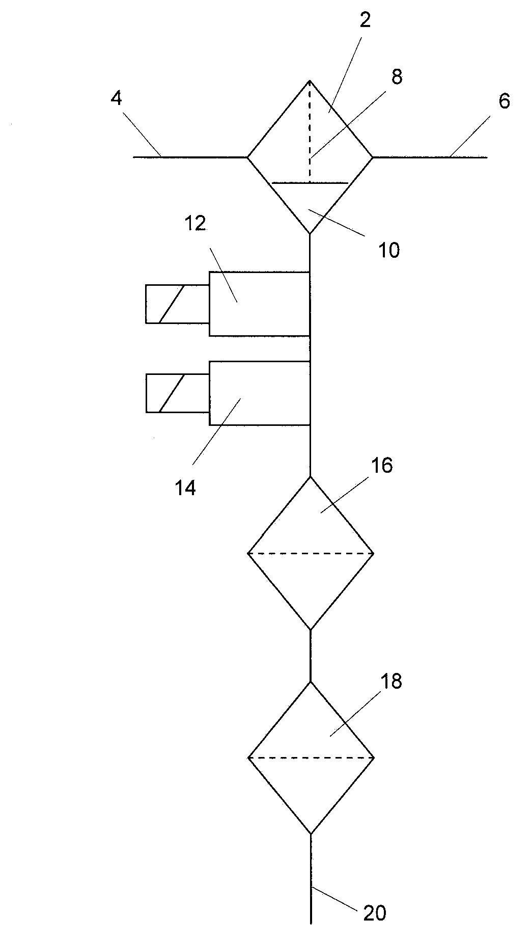
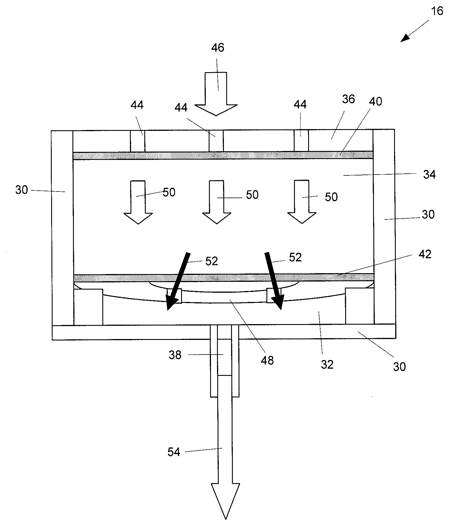
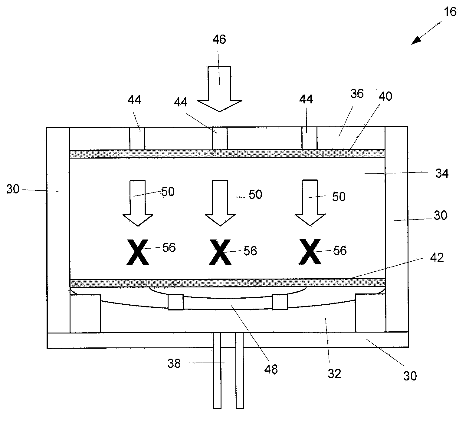
[0038] The present invention relates to a valve comprising a material arranged to absorb hydrocarbons from water flowing through the valve. In particular embodiments, the valve is incorporated into or attached to a water filter that further includes bulk filter material to absorb hydrocarbons from water passing through the filter. This valve has two functions. First, the valve's first function is that, for water contaminated with a small percentage of hydrocarbons, the filter material inside the valve progressively restricts the flow of water as the hydrocarbons are absorbed. The rate of restriction is selected to, when the valve is used in conjunction with a water filter further having bulk filter material, reduce the flow of water through the valve below a minimum threshold before the bulk filter material is depleted. In other words, the flow of water through the valve is reduced below a minimum threshold (separately detectable) before the proportion of hydrocarbons in the ...


PUM


Abstract

The invention discloses a valve (16) comprising a housing (30), a valve filter media (34) and an actuator (48). The housing (30) defines a chamber (32) having an inlet (44) and an outlet (48). The valve filter media (34) is positioned within the chamber (30) and arranged such that liquids flowing between the inlet (44) and the outlet (48) pass through the valve filter media (34). The valve filter media (34) is arranged to absorb hydrocarbons causing the valve filter media (34) to change its material properties thereby restricting the flow of liquids through the valve (16) and increasing the pressure differential across the valve filter media (34). The actuator (48) has at least a first portion positioned within the housing chamber (32). If the pressure differential across the valve filter media (34) exceeds a predetermined threshold the valve filter media (34) is arranged to bear against the actuator (48) causing the actuator (48) to restrict the flow of liquids through the valve (16).

Description

technical field [0001] The present invention relates to a valve. In particular, the present invention relates to a valve arranged to prevent the discharge of water from a water filter when the discharged water may be contaminated with a predetermined proportion of hydrocarbons. Certain embodiments of the invention relate to a water filter valve configured to restrict the flow of hydrocarbon-based fuels such as diesel and biodiesel. Embodiments of the present invention may form part of a water filter used to remove hydrocarbons and other contaminants from water separated from fuel in a fuel filter within a liquid fuel supply system. Background technique [0002] Fuel supply systems, especially vehicle fuel systems, typically include at least one fuel filter to remove water and other contaminants from the fuel. For medium and heavy duty trucks, there may be multiple fuel filters to gradually filter water, large particle contaminants and particulates from the fuel supply syst...

Claims


Application Information

Patent Timeline
Patent Type & Authority Applications(China)
IPC IPC(8): F02M37/22B01D36/00F16K31/00B01D17/02F02M37/28F02M37/34F02M37/48
CPCB01D17/0202B01D36/008F16K31/001Y10T137/1624Y10T137/2076Y10T137/3006Y10T137/7736F02M37/28F02M37/34F02M37/48C02F1/28
Inventor 菲利普·罗伯特·科里
Owner PARKER HANNIFIN MFG LTD
Learn More