Quantitative supply mechanism for trace medicine liquid
A technology of quantitative supply and liquid medicine, which is applied in the field of precise control of trace supply of insulin, anesthetics, and biochemical analysis reagents. Simple control and reliable structure
- Summary
- Abstract
- Description
- Claims
- Application Information
AI Technical Summary
Problems solved by technology
Method used
Image
Examples
Embodiment 1
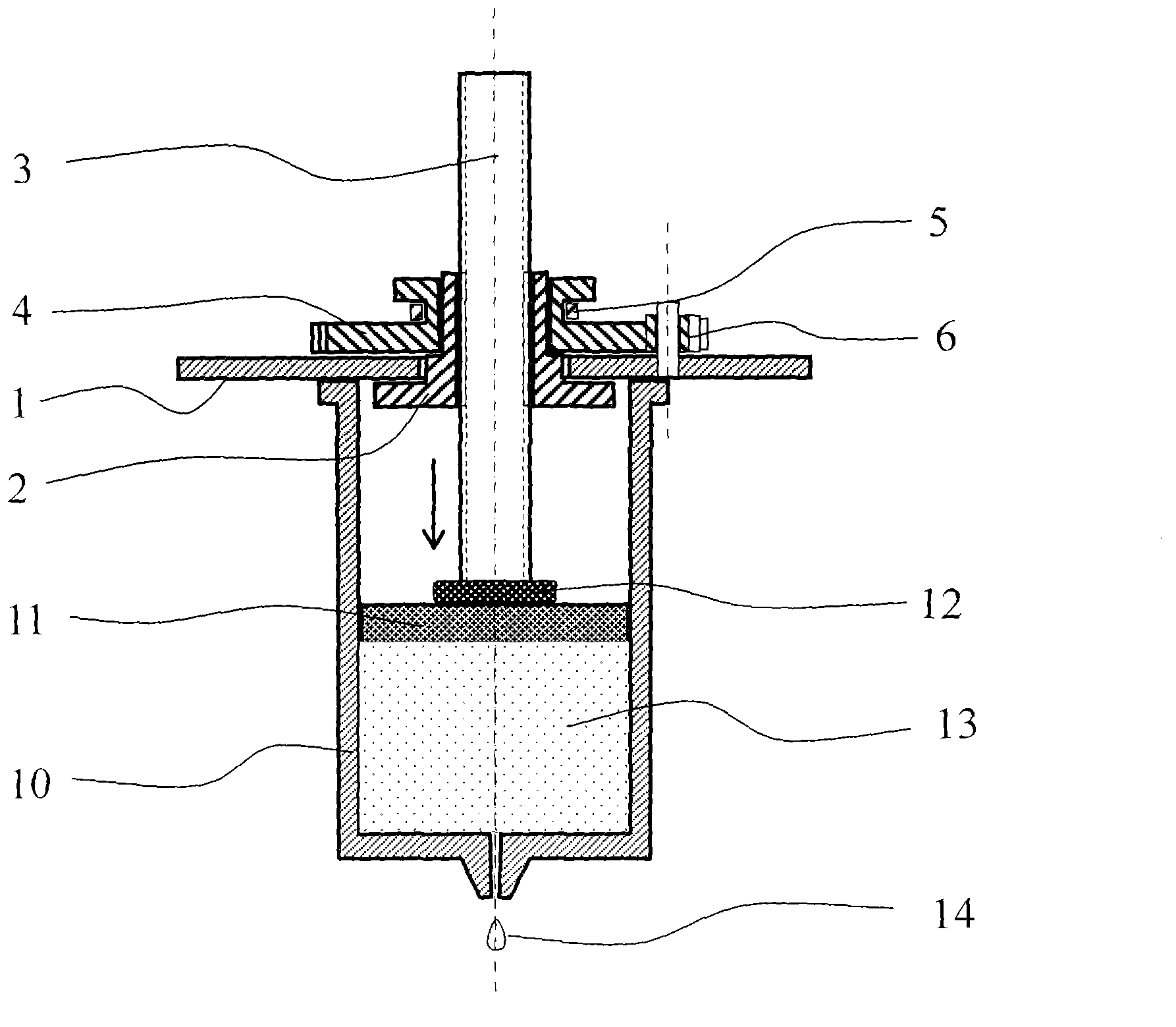
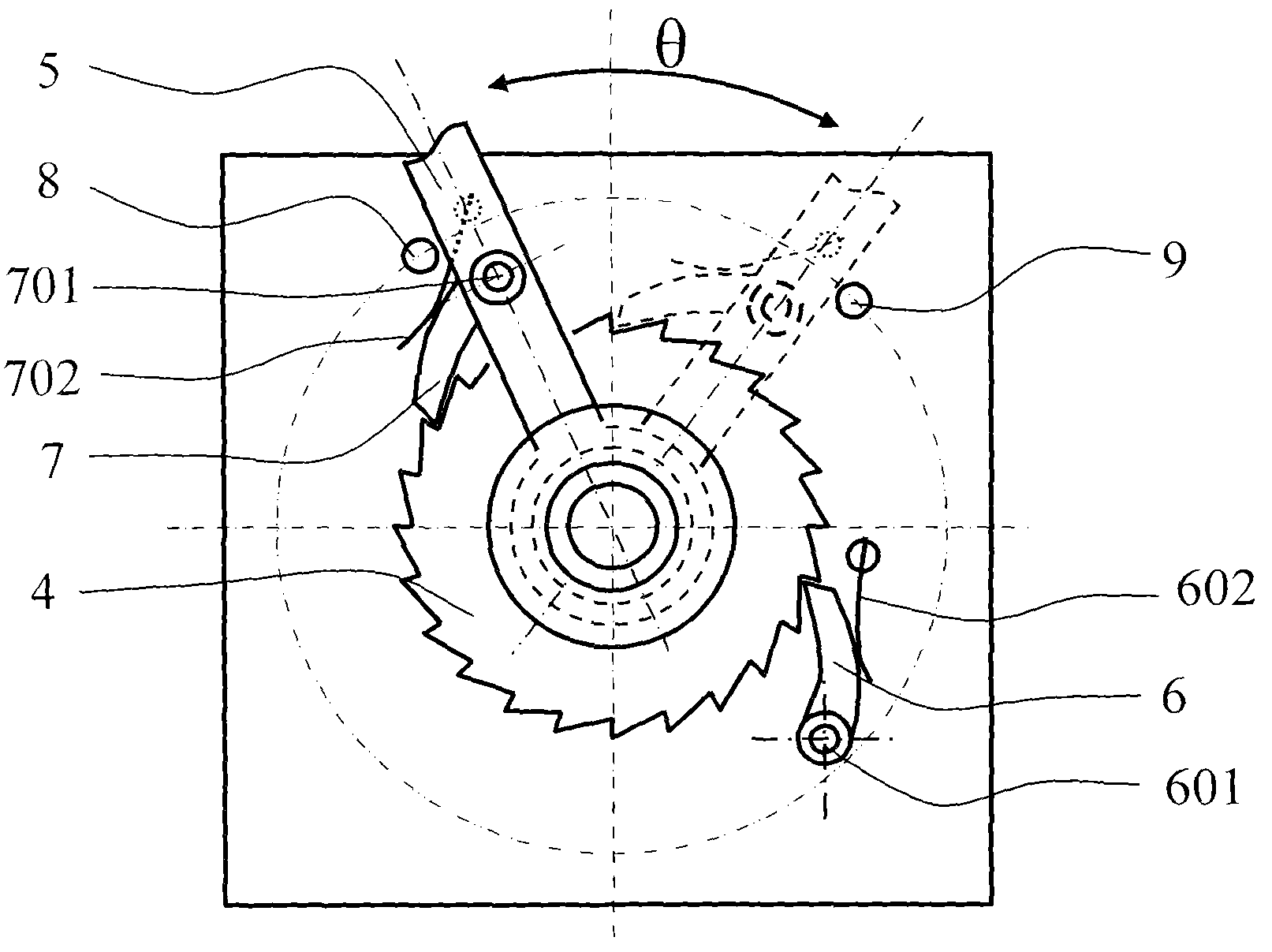
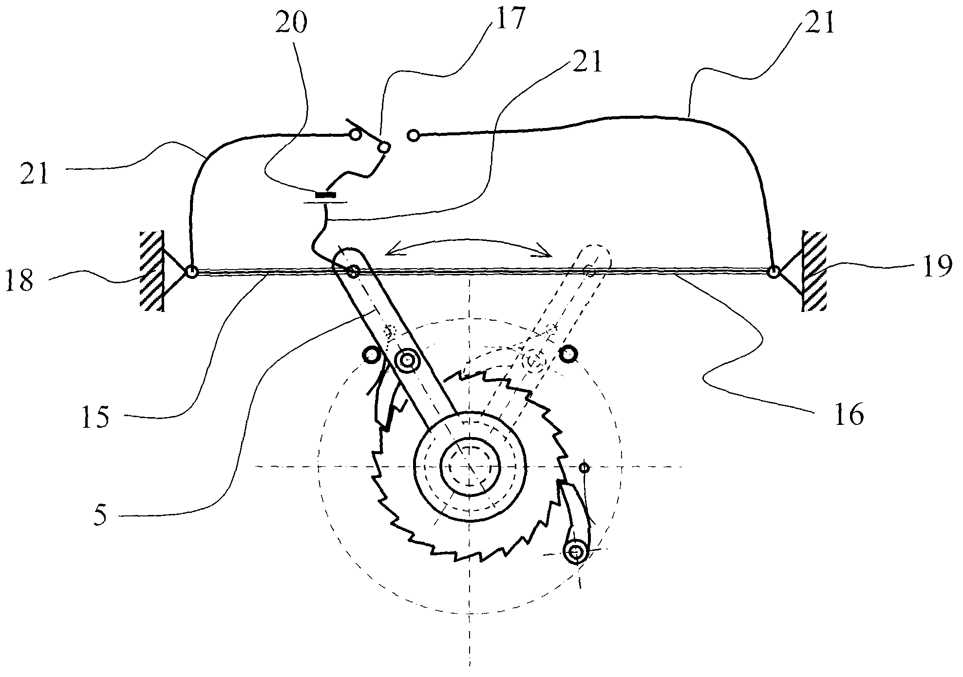
[0045] The present invention comprises bracket 1, screw nut 2, screw rod 3, ratchet 4, swing lever 5, non-return ratchet 6, active ratchet 7, left limit pin 8 and right limit pin 9, medicine bag 10 and medicine bag Balloon piston 11. A screw nut 2 is installed in the hole of the bracket 1, and a ratchet 4 is fixed on the screw nut 2. The combination of the screw nut 2 and the ratchet 4 can rotate in the hole of the bracket 1, but cannot move in the axial direction. A fork 5 is installed on the ratchet 4, and the fork 5 can rotate around the ratchet 4. The screw mandrel 3 and the nut 2 are connected by threaded fit. A screw washer 12 is fixedly installed at the lower end of the screw mandrel 3 . There is a rotary shaft 701 on the swing bar 5, and the active pawl 7 is installed on the shaft 701. The active pawl spring sheet 702 fixed on the swing bar provides a continuous active force for the active pawl 7, ensuring that the active pawl 7 is in contact with the active pawl. R...
Embodiment 2
[0057] Figure 4 and Figure 5 In the shown, as the invention described in Embodiment 1, the difference is: what is fixed on the screw nut 3 is not a ratchet wheel, but a worm wheel 22, and the worm wheel 22 is engaged with the worm gear rod 23, and the worm gear rod 23 passes through the bearing support 24 and 25 are installed on the support 1. One end of the worm gear 23 is fastened with a ratchet 4 and a fork 5 , and the fork 5 can rotate around the worm 23 axis. On the side plate 26 of the support, a non-return pawl rotating shaft 601 and a non-return pawl spring sheet (602) are installed. The non-return pawl 6 is installed on the non-return pawl rotating shaft 601. 602 The non-return pawl 6 provides a continuous force to ensure the contact between the non-return pawl 6 and the ratchet teeth of the ratchet 4 to prevent the ratchet 4 from turning backwards. There is a rotary shaft 701 on the swing bar 5, and the active pawl 7 is installed on the shaft 701. The active paw...
Embodiment 3
[0059] Figure 6As shown, the difference of the present invention as described in the second embodiment is that on the basis of the second embodiment, a screw reset mechanism is added. A left guide post 27 and a right guide post 28 are fixedly installed on the support 1, and the upper ends of the left guide post 27 and the right guide post 28 are fixed with the upper support 29. A slide plate 30 is installed on the guide post. The slide plate 30 can slide up and down along the left guide post 27 and the right guide post 28 . The upper end of the screw mandrel 3 is provided with a step to form a shaft head 31, and the shaft head 31 passes through the hole of the slide plate 30 and can rotate in the hole. A gear 32 is fixedly mounted on the shaft head 31 . Due to the limitation of the step on the screw mandrel 3 and the gear 32, the slide plate 30 and the screw mandrel 3 cannot move relative to each other, and the screw mandrel 3 and the gear 32 can rotate together. A motor ...
PUM
 Abstract
Description
Claims
Application Information
 - R&D
- Intellectual Property
- Life Sciences
- Materials
- Tech Scout
- Unparalleled Data Quality
- Higher Quality Content
- 60% Fewer Hallucinations
Browse by: Latest US Patents, China's latest patents, Technical Efficacy Thesaurus, Application Domain, Technology Topic, Popular Technical Reports.
© 2025 PatSnap. All rights reserved.Legal|Privacy policy|Modern Slavery Act Transparency Statement|Sitemap|About US| Contact US: help@patsnap.com


