
Tail gas recovery device based on pressure balance control method

A technology of balance control and tail gas recovery, applied in separation methods, chemical instruments and methods, sulfur and halogen compounds, etc. Achieve zero-emission and recycling, avoid test data drift, and strong recovery capabilities

Active Publication Date: 2013-12-25
HENAN RELATIONS
View PDF4 Cites 12 Cited by
  • Summary
  • Abstract
  • Description
  • Claims
  • Application Information

AI Technical Summary

Problems solved by technology

[0007] Through the investigation of the test exhaust gas recovery status of dozens of instrument manufacturers at home and abroad, it is found that: domestic instrument manufacturers have relatively poor environmental awareness, and the instruments are only equipped with exhaust pipes, and the test exhaust gas is directly discharged into the atmosphere through the exhaust pipe, without supporting equipment Exhaust gas collection equipment; some foreign instrument manufacturers have supporting exhaust gas collection / recovery equipment, but they all have relatively large limitations: such as the sulfur hexafluoride gas recovery device of the German GAS company, which uses a compressor and a recovery bag to control the exhaust gas produced in the test. The disadvantage of recycling sulfur hexafluoride tail gas is that the instrument is heavy (25.5KG), and the recovery bag has a large volume after collecting the gas, which is not convenient for on-site operation
The tail gas recovery device for sulfur hexafluoride gas test developed by some domestic units is bulky and heavy, weighing up to 45KG, which is not convenient for the recovery of sulfur hexafluoride gas test tail gas at the substation site

Method used


Image

  • Tail gas recovery device based on pressure balance control method

Examples


Embodiment Construction

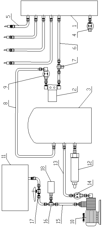
[0016] Such as figure 1 As shown, the tail gas recovery device based on the pressure balance control method of the present invention includes a buffer bottle 1, a primary recovery bottle 2 and a primary recovery compressor 3, the buffer bottle 1 is provided with a differential pressure sensor 4, and the buffer bottle 1 The air inlet is connected with at least one air inlet pipe 5, and the air inlet pipe 5 of the present embodiment is provided with four, and the air outlet of the buffer bottle 1 is connected with the air inlet of the primary recovery compressor 3 through the first high-pressure pipe 6, and the first A high-pressure pipe 6 is provided with an electromagnetic proportional valve 7; the air outlet of the first-stage recovery compressor 3 is connected to the air inlet of the first-stage recovery bottle 2 through the second high-pressure pipe 8, and the second high-pressure pipe 8 is provided with a first electromagnetic valve. Valve 9.

[0017] The present inventio...


PUM


Abstract

The invention provides a tail gas recovery device based on a pressure balance control method. The device comprises a surge flask, a primary recover flask and a primary recovery compressor, wherein a micro differential pressure transducer is arranged on the surge flask; at least a gas inlet pipe is connected at a gas inlet of the surge flask; a gas outlet of the surge flask is connected with a gas inlet of the primary recovery compressor by a first high pressure pipe; an electromagnetic proportional valve is arranged on the first high pressure pipe; a gas outlet of the primary recovery compressor is connected with a gas inlet of the primary recover flask by a second high pressure pipe; a first electromagnetic valve is arranged on the second high pressure pipe. The device has a simple structure, is easy to operate and control, has small volume and light weight, completely eradicates the adverse effects of sulfur hexafluoride emitted in test processes and decomposition products of sulfur hexafluoride on environments and human bodies, achieves zero emission and recycling of sulfur hexafluoride, has economic, environmental and safety triple benefits and can be broadly applied to collection of toxic tail gases or environment polluting tail gases generated in a laboratory environment or after detection by industrial field instruments.

Description

technical field [0001] The invention belongs to the technical field of recovery and utilization of laboratory or industrial waste gas and poisonous gas, and in particular relates to a tail gas recovery device based on a pressure balance control method. Background technique [0002] In the gas detection of various laboratories or industrial sites, due to the extensive economic development model in our country, the tail gas after the detection of such gases is usually directly emptied, which brings adverse effects to the natural ecological environment of our life. influences. [0003] For example, in the power industry, sulfur hexafluoride gas is widely used in various medium and high voltage electrical equipment because of its excellent insulation and arc extinguishing properties. However, this gas also has its limitations. According to the requirements of new gas acceptance, electrical equipment handover test standards and preventive test procedures, it is necessary to cond...

Claims


Application Information

Patent Timeline
Patent Type & Authority Applications(China)
IPC IPC(8): B01D53/00B01D53/48B01D53/68C01B17/45
Inventor 李建国汪献忠
Owner HENAN RELATIONS
Learn More