Hinge pin cutting mechanism

A cutting mechanism and pin shaft technology, applied in metal processing equipment, forming tools, manufacturing tools, etc., can solve problems such as low production efficiency, poor precision, complex structure, etc., and achieve high production efficiency, stable product quality, and good adaptability Effect

Inactive Publication Date: 2013-12-25
SUZHOU SHUNGE INTELLIGENT TECH
View PDF7 Cites 5 Cited by
  • Summary
  • Abstract
  • Description
  • Claims
  • Application Information

AI Technical Summary

Problems solved by technology

The existing pin shaft processing equipment has poor precision, complex structure and low production efficiency

Method used


Image

  • Hinge pin cutting mechanism
  • Hinge pin cutting mechanism

Examples


Embodiment Construction

[0018] The following will clearly and completely describe the technical solutions in the embodiments of the present invention. Obviously, the described embodiments are only some of the embodiments of the present invention, rather than all the embodiments. Based on the embodiments of the present invention, all other embodiments obtained by persons of ordinary skill in the art without making creative efforts belong to the protection scope of the present invention.

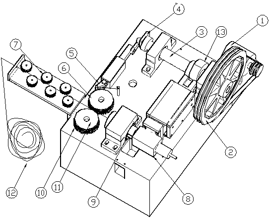
[0019] see Figure 1 to Figure 2 , the embodiment of the present invention includes:

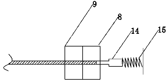
[0020] A pin shaft cutting mechanism, comprising: a bracket, a transmission main shaft 3, a spring 5, a cam 13, a push rod, a static cutting module 9, a dynamic cutting module 8 and a blanking port.

[0021] One end of the transmission main shaft 3 is provided with a power wheel to provide power for the cutting system.

[0022] The push rod is provided with a sliding sleeve, and the push rod is arranged in the sliding sleeve to e...


PUM


Abstract

The invention discloses a hinge pin cutting mechanism, which comprises a bracket, a transmission main shaft, a spring, a cam, a push rod, a static cutting module, a movable cutting module and a blanking hole, wherein the bracket is provided with the transmission main shaft; the transmission main shaft is provided with the cam; the push rod is arranged vertical to the transmission main shaft; the cam is connected with the push rod; the movable cutting module is arranged at the front end of the push rod; the static cutting module and the movable cutting module are arranged in parallel; the blanking hole is formed below the movable cutting module. Through the way, the hinge pin cutting mechanism disclosed by the invention has the advantages of high reliability, compact structure, high adaptability, high automatic production efficiency, stable product quality, adjustable product size and the like; meanwhile, the hinge pin cutting mechanism has a wide market prospect in the field of chain transmission manufacturing equipment.

Description

technical field [0001] The invention relates to the field of chain drive manufacturing equipment, in particular to a pin shaft cutting mechanism. Background technique [0002] Chain drive is a transmission method that transmits the movement and power of the driving sprocket with special tooth shape to the driven sprocket with special tooth shape through the chain. Chain transmission has many advantages. Compared with belt transmission, there is no elastic sliding and slipping phenomenon, the average transmission ratio is accurate, the work is reliable, and the efficiency is high; the transmission power is large, the overload capacity is strong, and the transmission size is small under the same working conditions; the required tension The tightening force is small, and the pressure acting on the shaft is small; it can work in harsh environments such as high temperature, humidity, dust and pollution. The existing pin shaft processing equipment has poor precision, complicated ...

Claims


Application Information

Patent Timeline
Patent Type & Authority Applications(China)
IPC IPC(8): B21D28/02B21D37/18
Inventor 戴双林何汉朝青克学熊家帮
Owner SUZHOU SHUNGE INTELLIGENT TECH
Why Eureka
Try Eureka