Riveting stamping mechanism for pulley retaining rings

A stamping riveting and retaining ring technology, which is applied in the field of stamping riveting mechanism for pulley retaining rings, can solve the problems of low processing efficiency, affecting product appearance, poor reliability of hammering riveting processing, etc., achieves low cost of cast iron, improves riveting efficiency, and plasticity The effect of small deformation

Inactive Publication Date: 2013-12-25
CHENGDU SILVERTECH TIMING PULLEYS MFG
View PDF0 Cites 6 Cited by
  • Summary
  • Abstract
  • Description
  • Claims
  • Application Information

AI Technical Summary

Problems solved by technology

[0004] For the riveting process of the pulley retaining ring in the above-mentioned prior art, the retaining ring and the pulley are fixed by hammering. After the riveting is completed, grooves are often left on the surface of the retaining ring, which affects the appearance of the product, and the hammering riveting process To solve the problems of poor reliability and low processing efficiency, the invention provides a punching and riveting mechanism for pulley retaining ring

Method used


Image

  • Riveting stamping mechanism for pulley retaining rings

Examples


Embodiment 1

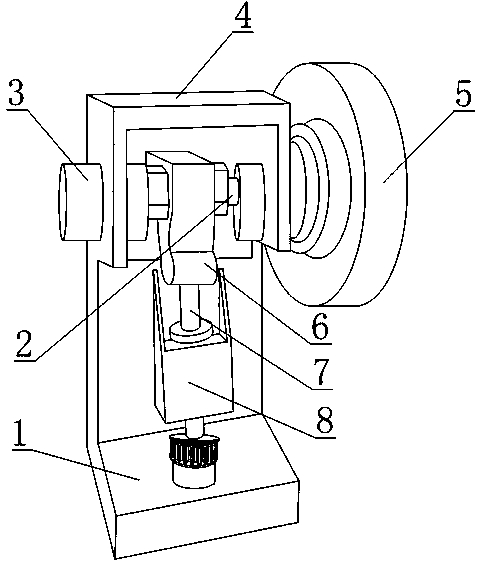
[0026] like figure 1 As shown, the pulley retaining ring punching riveting mechanism includes a drive shaft 2, a frame 4, two bearing boxes 3, a cam system 6, a rivet head rod 7 and a rivet head seat 8, and the two bearing boxes 3 are fixed Connected to the frame 4 , bearings are provided in the bearing housings 3 , the transmission shaft 2 and the inner rings of the bearings in the two bearing housings 3 are in an interference fit, and the cam system 6 includes a shell fixed on the frame 4 . The body and the cam fixedly connected with the transmission shaft 2, the rivet head seat 8 is fixedly connected to the frame 4, the rivet head rod 7 is partially located in the rivet head seat 8, and the rivet head rod 7 is located at any diameter of the cam up direction.

[0027] One end of the drive shaft 2 is connected to the drive motor, the rotational motion of the drive motor rotor is finally transmitted to the drive shaft 2, the drive shaft 2 drives the cam to rotate, and the cam...

Embodiment 2

[0029] This embodiment is further improved on the basis of Embodiment 1, such as figure 1 As shown, the rivet head seat 8 is a hollow structure, the rivet head rod 7 is also provided with an annular protrusion, and also includes a spring, the rivet head rod 7 is partially located in the center hole of the spring, and the spring is located in the rivet head In the hollow structure of the seat 8, both ends of the spring are in contact with the rivet head seat 8 and the annular protrusion respectively.

[0030] The purpose of the spring is that when the large diameter section of the cam is separated from the rivet head rod 7, the spring rebounds, and the rivet head rod 7 moves in the direction of the cam under the action of the spring force, that is, the rivet head rod 7 automatically resets, which is convenient for the next riveting. .

[0031] A flywheel 5 is also included, and the flywheel 5 is fixedly connected to the transmission shaft 2 .

[0032] The provided flywheel 5 ...


PUM

PropertyMeasurementUnit
thicknessaaaaaaaaaa

Abstract

The invention discloses a stamping riveting mechanism for pulley retaining rings. The stamping riveting mechanism comprises a transmission shaft, a frame, two bearing boxes, a cam system, a rivet shank and a rivet holder. The bearing boxes are fixed at corresponding positions on the frame. Each bearing box is provided with a bearing inside. The transmission shaft is in interference fit with inner rings of the bearings. The cam system comprises a housing fixed on the frame and a cam fixedly connected to the transmission shaft. The rivet holder is fixedly connected to the frame. The rivet shank partly locates in the rivet holder. The axial direction of the rivet shank is along the radial direction of the cam. The stamping riveting mechanism is simple in structure, convenient to produce and use, effective in riveting and high in riveting efficiency.

Description

technical field [0001] The invention relates to the field of mechanical processing riveting equipment, in particular to a punching riveting mechanism for a pulley retaining ring. Background technique [0002] In the synchronous belt drive, in order to prevent the deviation phenomenon caused by the non-parallel axis of the pulley, it is usually necessary to set a retaining ring on one side (or both sides) of the pulley. [0003] In the prior art, the retaining ring can be fastened to the side of the pulley by screws. At this time, it is necessary to make corresponding through holes and threaded holes on the retaining ring and the pulley and assemble them. The process is complicated and the cost is high; When it is not suitable to use fasteners such as screws to connect due to the limitation of the pulley structure size and other factors, riveting, spot welding and other methods can also be used to connect the pulley and the retaining ring. However, the thermal stress generate...

Claims


Application Information

Patent Timeline
Patent Type & Authority Applications(China)
IPC IPC(8): B21D39/00
Inventor 刘选明刘黎竞
Owner CHENGDU SILVERTECH TIMING PULLEYS MFG
Why Eureka
Try Eureka