
Method and device for welding water-wheel socket ring

A welding method and water turbine technology, applied in welding equipment, arc welding equipment, manufacturing tools, etc., can solve the problems of affecting operator safety and welding level, unsuitable for connecting welds, and high welding preheating temperature, so as to solve the problem of welding posture Limited, improved welding quality stability, continuous effect of welding process

Active Publication Date: 2015-05-27
DONGFANG ELECTRIC MACHINERY
View PDF6 Cites 1 Cited by
  • Summary
  • Abstract
  • Description
  • Claims
  • Application Information

AI Technical Summary

Problems solved by technology

[0005] (2) High welding preheating temperature
In a small semi-enclosed space, high temperature greatly affects the operator's safety and welding level;
[0006] (3) Seat ring components are all thick plates, with a large amount of welding filling and a long duration
However, the submerged arc welding process in this scheme is only used for the tailor welding of individual parts of the upper and lower ring plates, and is not suitable for the connection weld between the fixed guide vane and the upper and lower ring plates after the seat ring structure is assembled, so it is not suitable The above-mentioned difficulty in seat ring assembly and welding is not solved

Method used


Image

  • Method and device for welding water-wheel socket ring
  • Method and device for welding water-wheel socket ring
  • Method and device for welding water-wheel socket ring

Examples


Embodiment 1

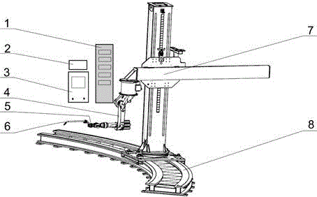
[0050] From figure 1 It can be seen that the present invention designs a robot automatic welding system according to the structural characteristics of the water turbine seat ring 9 and the welding process, mainly consisting of a robot body 4, robot external walking platforms 7, 8, a computer control system 1, a welding power supply 3, and a welding wire feeding mechanism 2 , robot welding torch 6, anti-collision sensor 5 and other parts.

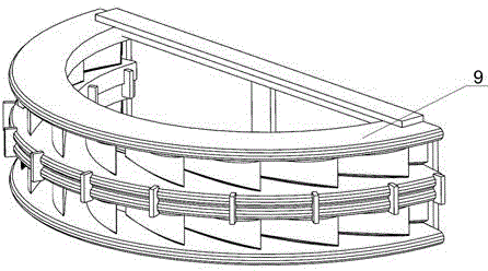
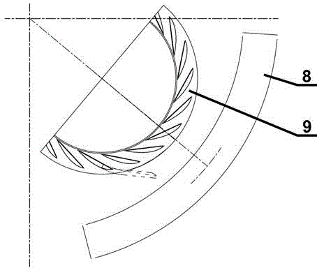
[0051] According to the structural characteristics of the water turbine seat ring 9 as a whole being ring-shaped and large in volume, an external walking platform of the robot is established on the periphery of the water turbine seat ring 9, which is composed of a cross carriage positioner 7 and an arc guide rail 8. The cross carriage positioner 7 is vertically installed on the arc guide rail 8, and the position adjustment in the horizontal and height directions is realized through the cross carriage positioner 7, and the position adjustment...

Embodiment 2

[0065] The difference between this embodiment and Embodiment 1 is that the robotic automatic welding system adopts another process layout, such as Figure 5 shown. Adjust the position of the external mobile platforms 7 and 8 of the robot and the posture of the robot body 4, and perform the automatic welding process of the robot on the inner circle side of the turbine seat ring 9. For some welds of the turbine seat ring 9 , performing welding from the inner side has better welding torch accessibility and welding operability, such as the back weld of the fixed guide vane of the turbine seat ring 9 .


PUM

PropertyMeasurementUnit
radiusaaaaaaaaaa
lengthaaaaaaaaaa

Abstract

The invention provides a method and a device for welding a water-wheel socket ring. The method includes that for generation of welding tracks, establishing a three-dimensional model of a water-wheel socket ring according to size, assembly and positional relation of each part, taking feature points on an intersection line of fixed guide vanes and upper and lower annular plates every other 50-100mm, and matching all control points to obtain the continuous welding tracks of an individual fixed guide vane; integrally translating the welding tracks of the individual fixed guide vanes on the three-dimensional model of the water-wheel socket ring to perform local modification, and continuously generating the welding tracks of the whole water-wheel socket ring; assembling the water-wheel socket ring; pre-heating prior to welding; using a robot welding gun for automatic welding. By the method, a robot welding process is continuous and stable, welding quality stability is remarkably improved, and welding efficiency is improved by 3-4 times as compared to that of manual welding; labor intensity and security risk of a welding operator are lowered; welding lines generated are regular in shape and attractive, and the qualified rate of flaw detection is higher than that of the same type by manual welding.

Description

technical field [0001] The invention relates to the technical field of manufacturing a seat ring of a hydroelectric generator, in particular to a robot automatic welding method and a device for a seat ring of a water turbine. Background technique [0002] The seat ring is an important buried part of the hydro-generator, which will bear the weight of the unit, the weight of the concrete, the axial water thrust of the runner and the internal water pressure of the volute, and should have sufficient strength, rigidity and stability. The process places extremely high demands. The seat ring is mainly welded by an upper ring plate, a lower ring plate and a certain number of fixed guide vanes, and each fixed guide vane is connected to the upper and lower ring plates by welding. The structure of the seat ring is relatively complex, the welding is difficult, and the quality of the weld seam is high, which puts forward high requirements for welding technology. [0003] Judging from t...

Claims


Application Information

Patent Timeline
Patent Type & Authority Patents(China)
IPC IPC(8): B23K9/16B23K9/235B23K9/12
Inventor 冯涛王平钟磊范阳阳梁城林松严靖郑光明
Owner DONGFANG ELECTRIC MACHINERY
Learn More