
Epoxy resin vacuum degassing mixing tank

A vacuum degassing and epoxy resin technology is applied in the field of transformers to eliminate local friction and overheating, improve efficiency and reduce equipment cost.

Active Publication Date: 2013-12-25
JIANGXI GANDIAN ELECTRIC
View PDF3 Cites 12 Cited by
  • Summary
  • Abstract
  • Description
  • Claims
  • Application Information

AI Technical Summary

Problems solved by technology

It can replace the complex and expensive lifter, thus solving three major problems: one is to replace the traditional lifter, which not only greatly reduces the cost of equipment, but also ensures the quality of mixing materials and improves the efficiency of mixing materials; Completely eliminate the hidden danger of local frictional overheating during the mixing process; the third is to smash the air bubbles in the mixture and fully expose them on the surface of the mixture for degassing, and finally form an epoxy resin vacuum degassing mixture Can

Method used


Image

  • Epoxy resin vacuum degassing mixing tank
  • Epoxy resin vacuum degassing mixing tank
  • Epoxy resin vacuum degassing mixing tank

Examples


Embodiment 1

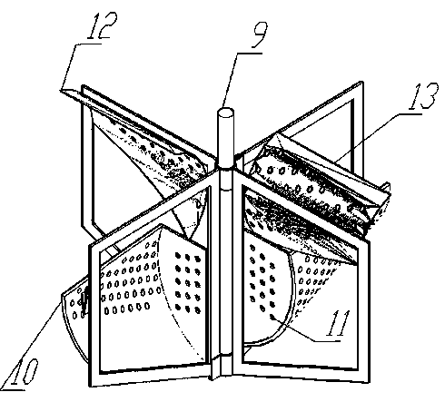
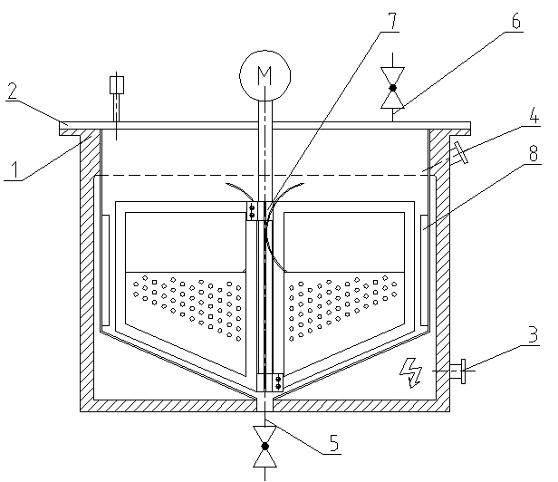
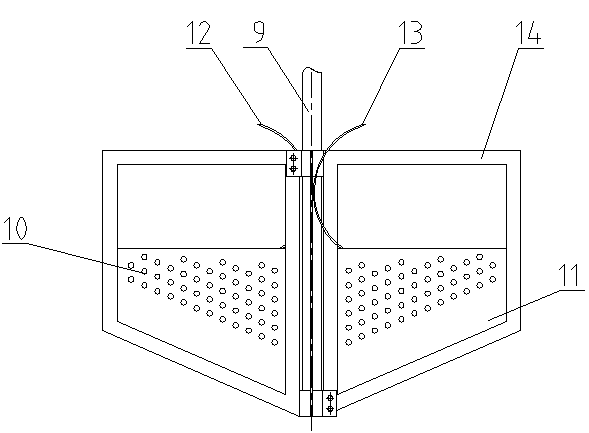
[0027] An epoxy resin vacuum degassing mixing tank, which consists of a tank body 1, a tank cover 2, an electric heating device 3, a material inlet 4, a material outlet 5, a vacuum valve 6, and a stirring assembly 7 driven by a motor, etc. Composition, the bottom of the tank body 1 is in an inverted conical shape, and a spoiler 8 is welded axially on the cylindrical inner wall side of the tank body 1 . The stirring assembly 7 is composed of a rotating shaft 9 , two pairs of stirring paddles in the upper and lower layers and a stirring flat steel frame 14 .

[0028] The paddles are distributed in upper and lower layers, the lower stirring paddles 10, 11 are below, the upper stirring paddles 12, 13 are above, and each paddle is placed at intervals between four right-angled trapezoids that form a 90° angle in space. On a flat steel rack.

[0029] The lower stirring blades 10, 11 are the lower stirring blades, which are welded by two parts: one is a right-angled trapezoidal thin ...


PUM


Abstract

The invention discloses an epoxy resin vacuum degassing mixing tank. The mixing tank comprises a tank body (1), a tank cover (2), an electric heating device (3), a feeding hole (4), a discharge hole (5), a stirring assembly (7) and a motor and is characterized in that the bottom of the tank body (1) is turbinate; spoilers (8) are axially arranged on the cylindrical inner wall sides of the tank body (1); a vacuum valve (6) is arranged on the tank cover (2) and is connected with a vacuum pump; the stirring assembly (7) comprises a rotating shaft (9), lower stirring blades (10, 11), upper stirring blades (12, 13) and a stirring flat steel frame (14). The mixing tank substantially reduces the equipment cost, is simple to manufacture, convenient to maintain and easy to clean, can not only ensure the quality of the mixture but also improve the mixing efficiency, thoroughly eliminates the hidden danger of local friction overheat possibly occurring in the mixing process, especially can achieve good stirring effects when a few mixtures exist and greatly improves the electrical strength and mechanical strength of a transformer.

Description

technical field [0001] The invention belongs to the technical field of transformers, and relates to the manufacture of filling epoxy resin cast transformer coils above 10KV level, in particular to an epoxy resin vacuum degassing mixing tank. Background technique [0002] The main key component of the filled epoxy resin cast transformer above 10KV level is the epoxy resin cast coil. Epoxy resin casting is the main process in the manufacture of epoxy resin casting coils. In this main process, the mixing process of epoxy resin and filler, curing agent, toughening agent and accelerator is the first key process of epoxy casting. If in the mixing process, the degassing of the epoxy resin mixture is not complete and the mixing is uneven, there will be air bubbles in the epoxy cast coil body, and the air bubbles will discharge under the action of a high-voltage electric field, resulting in an increase in the partial discharge of the entire product. large, the aging of the internal...

Claims


Application Information

Patent Timeline
IPC IPC(8): B29B7/16B29B7/22B29B7/84
CPCB29B7/845B29B7/86B29B7/16B29B7/22
Inventor 魏胜璋蔡新民魏海魏日成华伟辉
Owner JIANGXI GANDIAN ELECTRIC
Learn More