Railway wagon parking brake

A technology for parking brakes and railway wagons, applied to pneumatic brakes, railway car body parts, hydrostatic brakes, etc., can solve problems such as low work efficiency, difficult control, and high difficulty, and achieve convenient combination, reliable principle, and simple structure Effect

Active Publication Date: 2016-04-27
CRRC YANGTZE CO LTD
View PDF7 Cites 0 Cited by
  • Summary
  • Abstract
  • Description
  • Claims
  • Application Information

AI Technical Summary

Problems solved by technology

However, it also has major defects: first, the braking force of the train depends on the strength of the operator, which is difficult to control due to human factors, resulting in inconsistent braking force of the entire train; second, it is highly dependent on the operator, There is a situation where the operator forgets to apply the brakes to relieve or misuse the vehicle before the vehicle is running, resulting in no disengagement or insufficient disengagement between the wheel tiles, causing safety hazards such as vehicle tread abrasions; third, for the entire train of vehicles, it is necessary to Carrying out the manual operation of braking to stop or braking release one by one is time-consuming and laborious, and the work efficiency is very low
[0006] Because the integrated parking brake device has the following deficiencies: first, the principle structure is complicated, and the product manufacturing requirements are very high; second, when the locking mechanism fails, it will affect the wind braking system of the train and increase the unsafety of driving. The third is to combine the development of train brake cylinders, which is very difficult

Method used


Image

  • Railway wagon parking brake
  • Railway wagon parking brake
  • Railway wagon parking brake

Examples


Embodiment Construction

[0041] The present invention will be further described in detail below in conjunction with the accompanying drawings and specific embodiments.

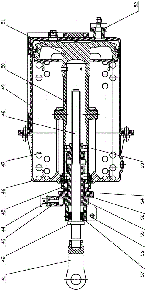
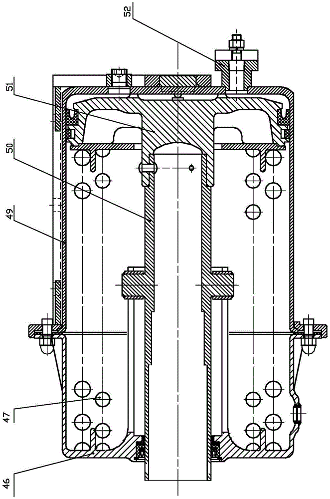
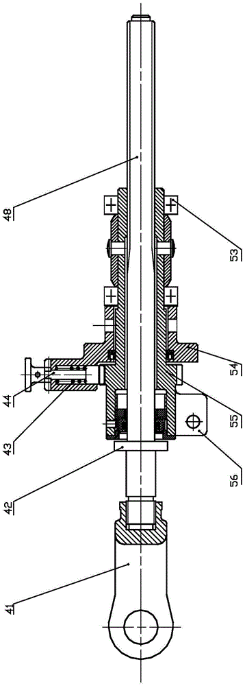
[0042] Such as Figure 1-7 As shown, the railway freight car parking brake of the present invention is mainly composed of an energy storage cylinder and a telescopic pull rod mechanism. The structure of each part is described as follows:

[0043] The energy storage cylinder consists of an energy storage cylinder body 49 and an energy storage cylinder head 46. The bottom of the energy storage cylinder body 49 is provided with a charging and exhaust flange joint 52. The energy storage cylinder body 49 is provided with a piston 51. The design stroke of the piston 51 is 160mm, an energy storage spring 47 is arranged between the backing plate at the bottom of the piston 51 and the energy storage cylinder cover 46, the center of the bottom of the piston 51 is connected with one end of the hollow piston rod 50, and the other end of the holl...


PUM


Abstract

The invention discloses a parking brake for a railway wagon. The parking brake for the railway wagon comprises an energy storage cylinder assembly and a telescopic pull rod mechanism, wherein the energy storage cylinder assembly comprises an energy storage cylinder body, a piston, an energy storage spring and a hollow piston rod. The telescopic pull rod mechanism comprises a pawl support connected with the hollow piston rod, and a ratchet nut cap and a pawl component which are arranged on the pawl support, the pawl component is connected and meshed with a ratchet of the ratchet nut cap in a pushing manner, a screw rod in screw-thread fit with a screw hole is arranged in the screw hole of the ratchet nut cap, the outer side end of the screw rod is connected with a pull rod head, and the pull rod head is directly connected with or is connected with a manual brake lever of a train foundation brake device through a lever in the working state. The parking brake for the railway wagon has the advantages that the structure is simple and compact, the maintenance and overhauling are convenient, the application is safe and reliable, the parking brake can be automatically released and used on the conditions that the normal driving, braking and mitigation functions of a train are not affected, traditional manual brakes and energy storage brakes can be replaced under severe operating environments, the labor cost and time are saved, and the safety and reliability are improved.

Description

technical field [0001] The invention relates to a parking brake technology for railway freight cars, in particular to a parking brake for railway freight cars. Background technique [0002] During the transportation of railway freight cars, when the vehicles stop normally or need to be parked on the track, freight yard or maintenance workshop due to failure or derailment, in order to ensure the safety of the staff, parking brakes must be implemented on a certain number of vehicles. Parking brake is an auxiliary backup braking technology for railway freight cars, which is used to keep the vehicle maintaining the braking force after the air braking force is eliminated, so as to prevent the vehicle from moving on the track and causing safety accidents. [0003] The traditional parking brake method of railway freight cars is mainly realized by the hand brake device, which applies the braking force to the wheel tread of the railway freight car by turning the hand wheel or swingin...

Claims


Application Information

Patent Timeline
Patent Type & Authority Patents(China)
IPC IPC(8): B61H11/06
Inventor 王高马驰任志望涂智文王浩文易新炳
Owner CRRC YANGTZE CO LTD
Why Eureka
Try Eureka