
Ionic membrane electrolytic bath

An ionic membrane electrolytic cell and current collector technology, applied in the electrolysis process, electrolysis components, cells, etc., can solve the problems of uneven current density distribution of electrolyte, uneven electrolyte concentration distribution, uneven current density distribution, etc. It can achieve the effect that the cell voltage drops significantly, the liquid concentration quickly tends to be uniform, and the current distribution is uniform.

Active Publication Date: 2013-12-25
BLUESTAR BEIJING CHEM MACHINERY
View PDF3 Cites 6 Cited by
  • Summary
  • Abstract
  • Description
  • Claims
  • Application Information

AI Technical Summary

Problems solved by technology

[0002] Existing unipolar ion-exchange membrane electrolyzers for the production of caustic soda contain an external circulation structure for the electrolyte. When energized and running, due to the absence of an internal circulation structure, the concentration of the electrolyte in the anode unit is unevenly distributed, resulting in the flow of the electrolyte The current density distribution is not uniform, which leads to an increase in the resistance of the electrolyte and a higher cell voltage
In addition, the structure of the cathode chamber of the existing ion-exchange membrane electrolyzer belongs to the type of electrolytic cell with pole spacing, the electrode mesh is large, the current density distribution is uneven, and the existence of the pole spacing will also increase the resistance of the electrolyte and the cell voltage.
However, the resistance of the electrolyte increases and the voltage of the tank increases, which will lead to high power consumption per ton of alkali and increase production costs.

Method used


Image

  • Ionic membrane electrolytic bath
  • Ionic membrane electrolytic bath
  • Ionic membrane electrolytic bath

Examples


Embodiment Construction

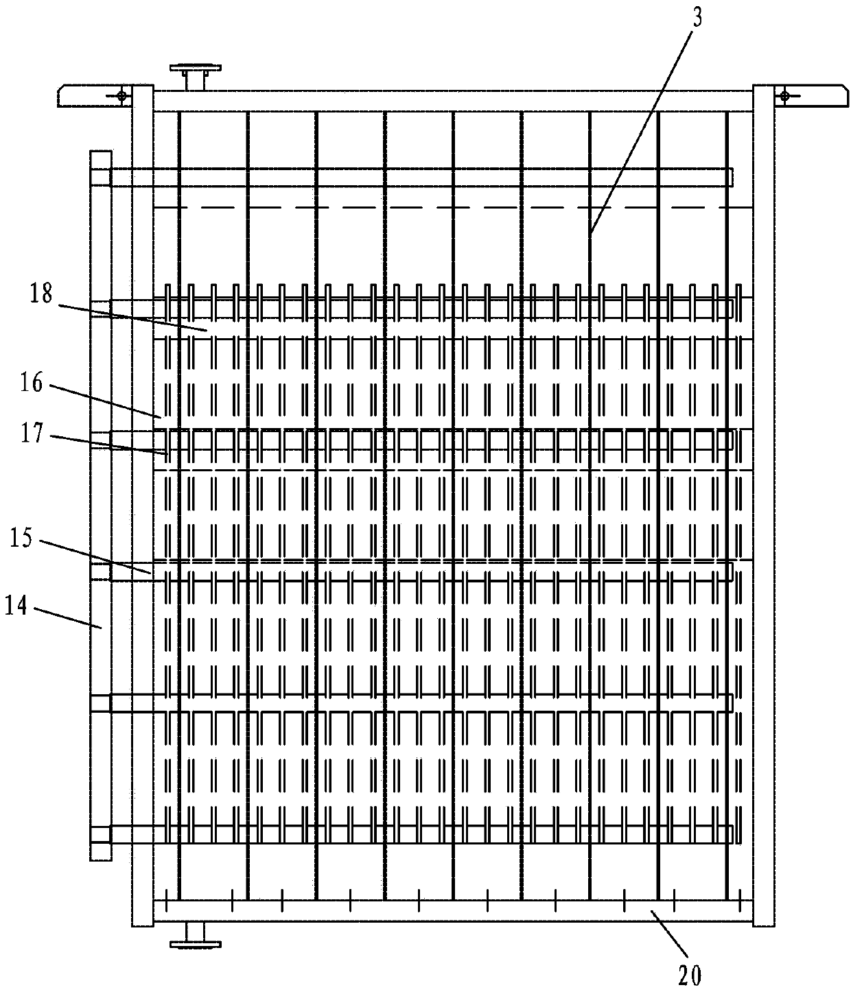
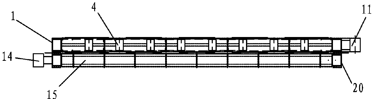
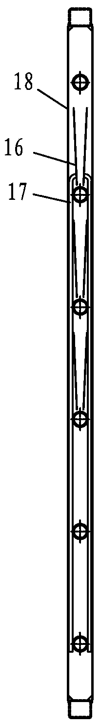
[0018] Such as figure 1 , figure 2 , Figure 4 and Figure 5 As shown, the ionic membrane electrolyzer of the present invention includes more than one anode unit and more than one cathode unit, and the cathode unit and the anode unit are juxtaposed in the order of a cathode unit, an anode unit, another cathode unit, and another anode unit Adhere to the setting, figure 2 Only a cathode unit and an anode unit are schematically drawn, and each cathode unit includes a cathode frame 1 arranged along the left and right vertical directions, the bottom end of the cathode frame 1 is provided with an inlet, and the top end of the cathode frame 1 is provided with an outlet , the front and rear sides of each cathode frame 1 are respectively provided with a support plate 2 made of expanded mesh. The plates 3 are fixedly connected, and the side ends of the multi-channel cathode ribs 3 are respectively fixedly connected with the inner wall of the cathode frame 1 where they are located....


PUM


Abstract

The invention relates to an ionic membrane electrolytic bath. A uniform liquid bubble-eliminating device is arranged between two anodes in each anode side frame, each uniform liquid bubble-eliminating device comprises a plurality of diversion pipes arranged along the vertical direction and a plurality of diversion circulating plate clamps, which are positioned in the anode side frame, the plurality of diversion pipes are arranged in a row along a left-and-right direction, a plurality of long strip-shaped through holes are formed in the side wall of each diversion pipe from top to bottom along the left-and-right direction, the plurality of diversion circulating plate clamps respectively penetrate through the through holes in one row of the plurality of diversion pipes along the left-and-right direction from different height positions, each pair of the diversion circulating plate clamps comprises two diversion circulating plates which are arranged side by side along a front-and-back direction, the plate surfaces of the circulating plates are positioned in the left-and-right direction, and the spacing interval between the lower edges of the two diversion circulating plates is smaller than that between the upper edges of the two diversion circulating plates. The invention aims at providing the ionic membrane electrolytic bath which can prolong the service life of an ionic membrane, reduce the consumption of electrical energy and reduce the production cost.

Description

technical field [0001] The invention relates to an ion membrane electrolyzer. Background technique [0002] Existing unipolar ion-exchange membrane electrolyzers for the production of caustic soda contain an external circulation structure for the electrolyte. When energized and running, due to the absence of an internal circulation structure, the concentration of the electrolyte in the anode unit is unevenly distributed, resulting in the flow of the electrolyte The current density distribution is also uneven, which in turn leads to an increase in the resistance of the electrolyte and a higher cell voltage. In addition, the structure of the cathode chamber of the existing ion-exchange membrane electrolyzer belongs to the type of electrolytic cell with a pole distance, the electrode mesh is large, and the current density distribution is uneven. The existence of the pole distance will also increase the resistance of the electrolyte and the cell voltage. However, the resistance...

Claims


Application Information

Patent Timeline
IPC IPC(8): C25B9/10C25B1/16C25B9/23
Inventor 郭立德刘秀明陈中元王伟红乔宵峰刘继东
Owner BLUESTAR BEIJING CHEM MACHINERY
Features
  • Generate Ideas
  • Intellectual Property
  • Life Sciences
  • Materials
  • Tech Scout
  • Unparalleled Data Quality
  • Higher Quality Content
  • 60% Fewer Hallucinations
Learn More