Shaft type flood spillway for reservoirs

A spillway and shaft-type technology, applied in water conservancy projects, sea area engineering, coastline protection, etc., can solve the problems of general energy dissipation function of spillway, large tailwater fluctuation and atomization, unreasonable structure of spillway, etc., and achieve good energy dissipation effect , sufficient energy dissipation and improved discharge capacity

Active Publication Date: 2015-04-29
STATE GRID CORP OF CHINA +2
View PDF8 Cites 8 Cited by
  • Summary
  • Abstract
  • Description
  • Claims
  • Application Information

AI Technical Summary

Problems solved by technology

Existing spillways generally consist of vertical shafts, drainage tunnels, chutes and stilling basins set on the dam of the reservoir; Potential safety hazards. In addition, the energy dissipation function of the existing spillway is relatively general, which makes the downstream local erosion problem more serious, with more accumulations, tail water fluctuation and atomization are relatively large

Method used


Image

  • Shaft type flood spillway for reservoirs
  • Shaft type flood spillway for reservoirs
  • Shaft type flood spillway for reservoirs

Examples


Embodiment

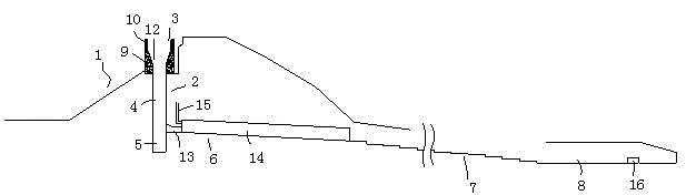
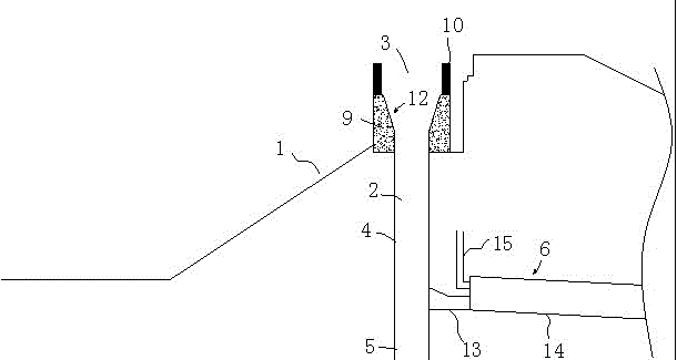
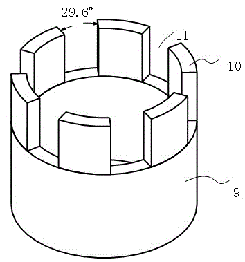
[0038] Example: A kind of vertical well spillway of a reservoir, constituted as figure 1 , figure 2 with Figure 4 As shown, the spillway includes a shaft 2 arranged on the reservoir dam 1. The shaft 2 includes an upper water inlet 3, a shaft section 4 connected to the water inlet 3, and an energy dissipation well 5 arranged below the shaft section 4; The lower part is provided with a drain hole 6, the drain hole 6 is connected with a stepped drain groove 7, and the stepped drain slot 7 is connected with a stilling pool 8. As attached image 3 As shown, the water inlet 3 is a cylindrical flat-topped weir 9, that is, the main body of the water inlet is a flat-topped weir, and the top of the weir is annularly provided with 6 branching piers 10, and there are water inlets 11 between the branching piers 10; The height of the branch pier 10 is 4m, and the width of the branch pier 10 is 1.0m. The inner arc radius of the branch pier 10 is r=4.5m, and the outer arc radius is R=5.5m; b...


PUM


Abstract

The invention discloses a shaft type flood spillway for reservoirs. The flood spillway comprises a shaft (2) arranged on a reservoir dam (1). The shaft (2) comprises a water inlet (3), a shaft section (4) and an energy dissipation well (5), wherein the water inlet (3) is arranged on the upper portion of the shaft (2), the shaft section (4) is connected with the water inlet (3), and the energy dissipation well (5) is arranged under the shaft section (4). The lower portion of the shaft (2) is provided with a water-brake cavity (6) which is connected with a stepped discharge chute (7), and the stepped discharged chute (7) is connected with a stilling pool (8). Further, each section is specifically modified in structure and size. Therefore, discharge capacity is greatly improved, and discharged water flows stably and smoothly. In addition, the shaft type flood spillway has the advantage of excellent energy dissipation effect.

Description

Technical field [0001] The invention relates to a shaft type spillway, in particular to a shaft type spillway that can be applied to reservoirs with various terrains. Background technique [0002] At present, with the gradual development of hydraulic resources in mountainous rivers in my country, the development of my country's hydropower project construction has entered a climax stage, especially in the western mountainous areas to build a large number of small and medium-sized hydropower stations. The water flow in natural river channels is generally slow, and the single-width flow is more evenly distributed along the river width. However, when dams, gates and other discharge structures were built in the river course, the flow conditions in the river course changed greatly. The discharge flow (compared to the water flow before the dam was not built) had a higher flow rate and a higher flow energy, which had a greater impact on the downstream river bed. Destructive power. If t...

Claims


Application Information

Patent Timeline
Patent Type & Authority Patents(China)
IPC IPC(8): E02B8/06
Inventor 张学清蒋海云马泾阳贺涌幸和生李立秋姜红伟蔡海涛殷康
Owner STATE GRID CORP OF CHINA
Why Eureka
Try Eureka