Magnetic pump

A magnetic pump and pump shaft technology, applied in the direction of pumps, pump devices, pump components, etc., can solve the problems of inability to popularize and apply, low corrosion resistance of bearing materials, and low bearing capacity.

Inactive Publication Date: 2013-12-25
浙江巨龙泵业有限公司
View PDF5 Cites 4 Cited by
  • Summary
  • Abstract
  • Description
  • Claims
  • Application Information

AI Technical Summary

Problems solved by technology

The magnetic pump in the prior art is prone to the following problems: the inner hole of the rolling bearing is installed on the plastic ring or plastic pipe protruding from the front pump casing. Since the plastic ring or plastic pipe is a thin-walled part, it cannot withstand the radial force generated by the water flow. Due to the cold flow and shrinkage of plastic between the bearing and the pump shaft, the relative movement between the bearing and the pump shaft will cause damage to the support; because the cage occupies more than half of the position, the balls are reduced, and the bearing capacity Very small; the bearings are made of traditional materials such as silicon nitride, silicon carbide, and zirconia, which have poor corrosion resistance and are easily corroded when encountering strong corrosive working media; since the cage cannot be made of brittle materials such as ceramics, it can only If it is replaced by inferior materials, the overall performance of the bearing will deteriorate. When the cage meets the granular working medium, it is easy to rub or collide with the particles in the working medium, resulting in premature failure of the cage; the sealing cover of the rolling bearing is made of rubber material. It is easy to be carbonized and burned when working in medium, and it will be swelled and destroyed when it encounters organic solvents
Although the technology has been proposed for nearly ten years, it cannot be widely applied
[0006] It can be seen from this that the working medium must not have particles, the magnetic pump cannot run idle, cannot be overloaded, and the bearing material has low corrosion resistance. These problems still need further research and solution in production practice.

Method used


Image

  • Magnetic pump
  • Magnetic pump
  • Magnetic pump

Examples


Embodiment Construction

[0028] In order to make the object, technical solution and advantages of the present invention clearer, the present invention will be further described in detail below in combination with specific embodiments and with reference to the accompanying drawings. It should be understood that these descriptions are exemplary only, and are not intended to limit the scope of the present invention. Also, in the following description, descriptions of well-known structures and techniques are omitted to avoid unnecessarily obscuring the concept of the present invention.

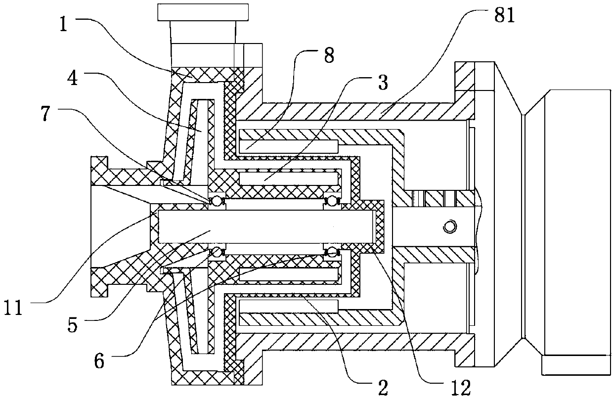
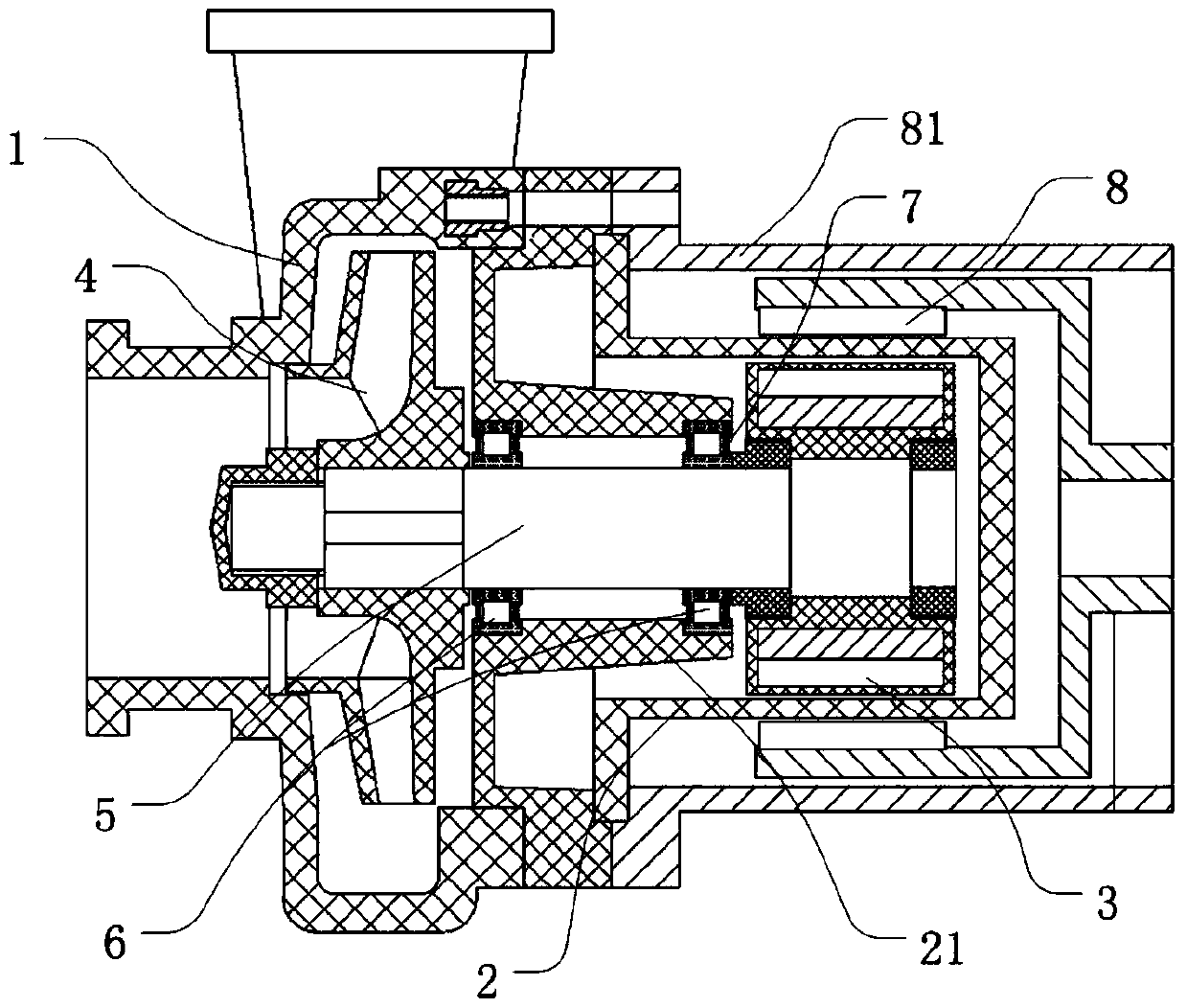
[0029] figure 1 It is a structural schematic diagram of the magnetic pump according to the first embodiment of the present invention. Among them, the magnetic pump mainly includes an outer magnetic assembly, a pump casing 1, an inner magnetic assembly, and an impeller 4 driven by the inner magnetic assembly. The pump casing 1 and the spacer 2 are closed to form a pump cavity. The cage of the magnet 3 is composed. When ...


PUM


Abstract

The invention provides a magnetic pump, which comprises a pump cavity, an inner magnetic assembly, an impeller, a pump shaft, two bearings and an outer magnetic assembly, wherein the pump cavity consists of a pump case and an isolation sleeve, the impeller is driven by the inner magnetic assembly, the two bearings are sheathed on the pump shaft, each bearing comprises a bearing inner ring, a rolling body, a bearing outer ring and a sealing cover, the sealing cover is arranged between the bearing inner ring and the bearing outer ring for protecting the rolling body, the outer magnetic assembly is used for driving the inner magnetic assembly to rotate under the effect of the external driving force, the pump shaft is a solid shaft, and the rolling bodies arranged in the bearings are densely distributed and arranged between the bearing inner ring and the bearing outer ring. The magnetic pump solves the problems that in the prior art, the bearings and the hollow pump shaft do not have the wear resistance, corrosion resistance or particle work medium resistance in the idle state, and the heavy load cannot be realized. The magnetic pump can realize the high-load heavy-load work under the condition of particular work media or corrosive environment, and in addition, the idle state can be realized.

Description

technical field [0001] The invention relates to a magnetic pump, in particular to a magnetic pump capable of idling and heavy load. Background technique [0002] In European and American pharmaceutical, chemical and petrochemical plants, non-leakage pumps can be seen everywhere, and most media other than water are transported by magnetic pumps. In addition, in addition to no leakage, leak-free pumps have many other advantages such as maintenance-free and long life. In the past two years, frequent leakage of liquid chlorine and other chemical media during transportation, poisonous gas pollution and even environmental damage caused by chemical plant explosions have made people aware of the importance of safe transportation of various media. How to reduce leakage has increasingly become an urgent issue to be considered in the production of enterprises and even in government supervision and legislation. The magnetic pump plays an important role in the conveying medium. [000...

Claims


Application Information

Patent Timeline
Patent Type & Authority Applications(China)
IPC IPC(8): F04D13/02F04D7/06F04D29/043F04D29/046F04D29/02
Inventor 李瑞李琼李瑜
Owner 浙江巨龙泵业有限公司
Why Eureka
Try Eureka