Modularized data center machine room air conditioning system

A data center and computer room air-conditioning technology, applied in air-conditioning systems, heating and ventilation control systems, heating and ventilation safety systems, etc., can solve problems such as difficult modular installation and management, complex structure, energy loss, etc., to facilitate standardization and reduce Work load, effect of eliminating energy loss

Active Publication Date: 2013-12-25
GUANGDONG HIWAVE TECH
View PDF7 Cites 27 Cited by
  • Summary
  • Abstract
  • Description
  • Claims
  • Application Information

AI Technical Summary

Problems solved by technology

[0009] Therefore, the technical problem to be solved by the present invention is that the data center room air-conditioning system in the prior art is not only complex in structure, but also has the problems of energy loss caused by mixing cold and hot air, high energy consumption, and difficult to realize modular installation and management. A modular data center computer room air conditioning system with simple and compact structure, separated cold and hot air, more energy-saving, and convenient for data center modularization

Method used


Image

  • Modularized data center machine room air conditioning system
  • Modularized data center machine room air conditioning system
  • Modularized data center machine room air conditioning system

Examples


Embodiment 1

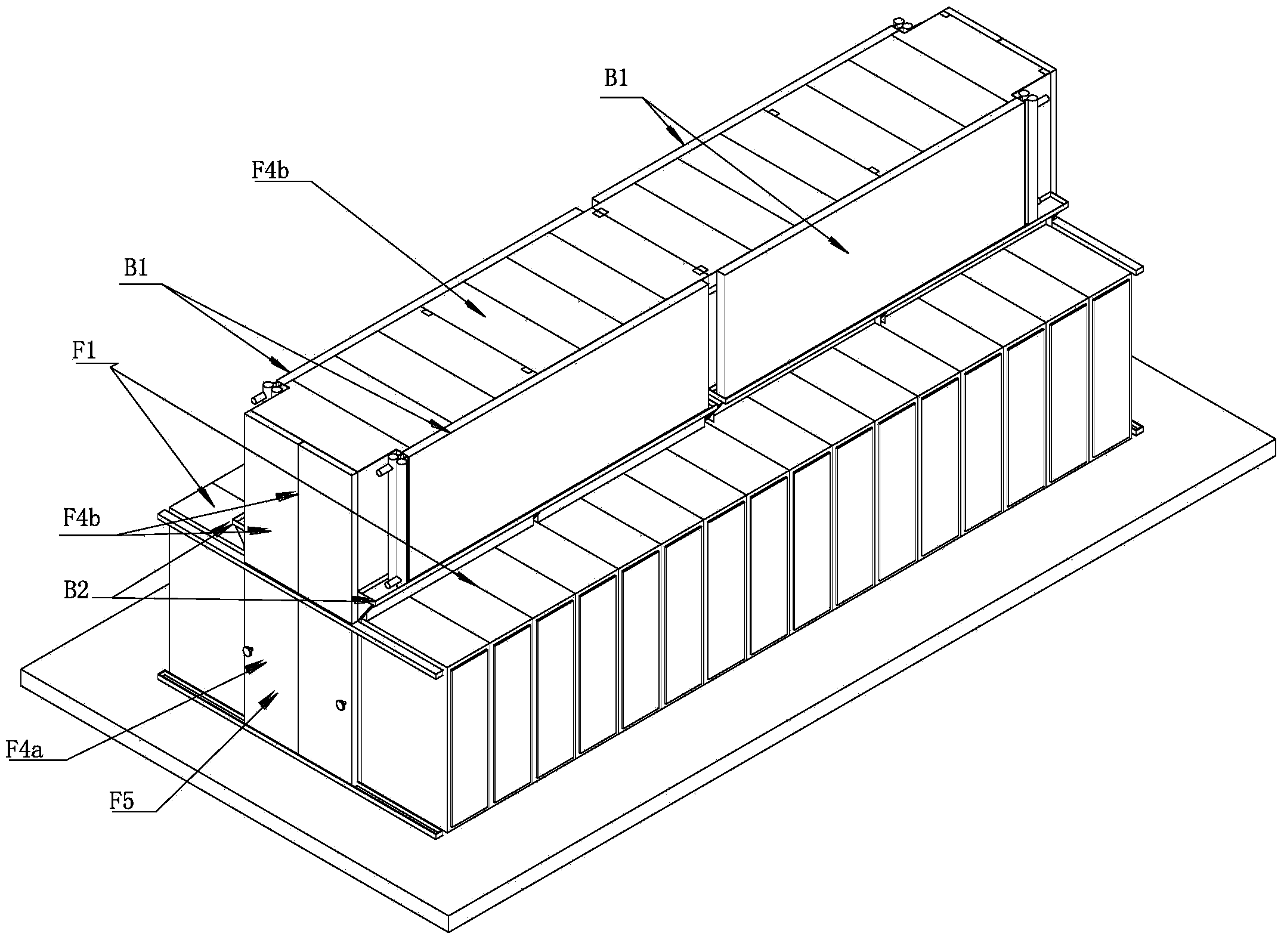
[0052] like Figure 5 and Image 6 As shown, a modular data center computer room air-conditioning system in Embodiment 1 includes an indoor device B and an outdoor device A, and the indoor device B includes

[0053] The installation bracket F3 is arranged on the floor of the machine room, and the left and right sides of the installation bracket F3 are suitable for facing two rows of cabinets F1 face to face or back to back;

[0054] Refrigeration heat exchanger: There are two rows on the left and right consistent with the row direction of the cabinet F1, which are respectively installed on the installation bracket F3, and the two rows of the refrigeration heat exchanger are arranged in an "A" shape opposite to each other. The upper part of the mounting bracket F3, the front and rear ends of the mounting bracket F3 are provided with a lower closing plate F4a, and the front and rear ends of the two rows of refrigeration heat exchangers are also provided with an upper closing pl...

Embodiment 2

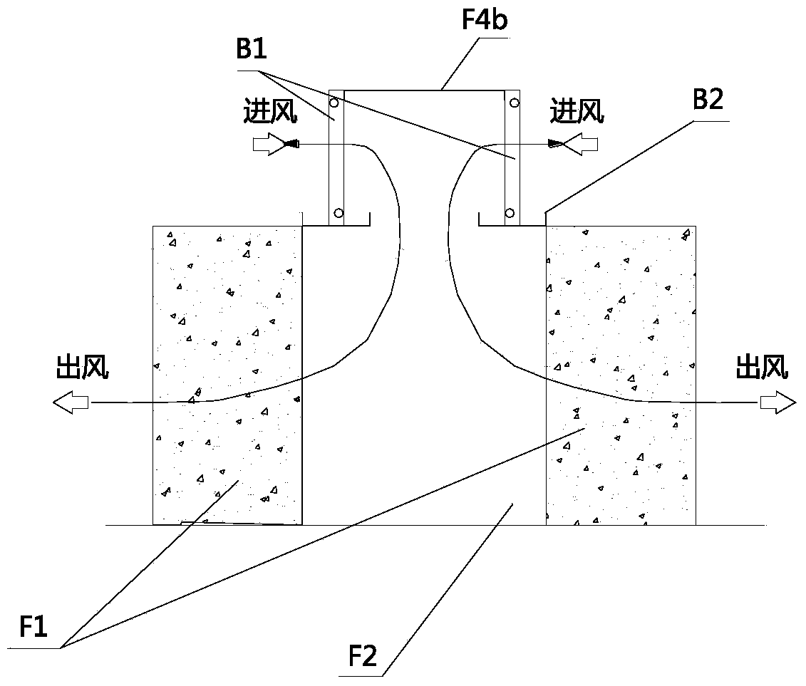
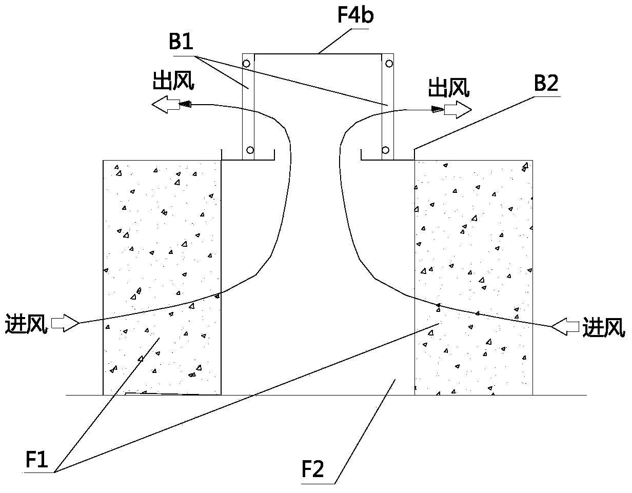
[0067] like image 3 and 4 As shown, different from Embodiment 1, in this Embodiment 2, the two rows of refrigeration heat exchangers can also be arranged vertically opposite to each other in the shape of "II" on the top of the installation bracket F3, and the installation bracket The front and rear ends of F3 are provided with lower closed plates F4a, the front and rear ends of the two rows of refrigeration heat exchangers, and the top are all provided with upper closed plates F4b, and the closed channel F2 is composed of the cabinet F1 and the lower closed plates F4a , the upper sealing plate F4b, and the refrigeration heat exchanger are directly enclosed. Of course, there are many ways to arrange the evaporator B1 on the upper part of the mounting bracket F3, which will not be described here.

Embodiment 3

[0069] like Figure 9As shown, the difference from Embodiments 1 and 2 is that the two rows of refrigeration heat exchangers are arranged vertically opposite to each other in the shape of "II" on the left and right sides of the installation bracket F3, which is suitable for the cabinets F1 arranged on the same side. The front or back is closely connected. In Embodiment 3, the two rows of fans are also installed vertically close to the cooling heat exchanger on the installation bracket F3, preferably the back of the cabinet F1 is directly connected to the cooling heat exchanger. The solution in Embodiment 3 is very suitable for a computer room that is not too high.

[0070] In the above three embodiments, the evaporator B1 can also be replaced by a cold water cooling surface cooling heat exchanger.


PUM


Abstract

The invention relates to a modularized data center machine room air conditioning system. The modularized data center machine room air conditioning system comprises an indoor device and an outdoor device, wherein the indoor device comprises a mounting bracket and refrigerating heat exchangers; the mounting bracket is arranged on a machine room floor; the left and right sides of the mounting bracket are oppositely provided with two rows of cabinets face to face or back to back; two rows of refrigerating heat exchangers are arranged in the direction which is the same as the arrangement direction of the cabinets and are oppositely arranged on the mounting bracket respectively; the mounting positions of the refrigerating heat exchangers on the mounting bracket meet that air outlets or air inlets of the refrigerating heat exchangers are directly communicated with air inlets or air outlets of the cabinets or communicated through a common closed passage. According to the modularized data center machine room air conditioning system, after the independent indoor device is arranged, the data center server cabinets can be conveniently combined with the modularized data center machine room air conditioning system to form an air flow cooling circulation system of the server and the indoor device, hot air which comes out from the server enters the indoor refrigerating system through a path which is as short as possible, and the energy loss caused by mixing of cold air and hot air in an indoor air conditioner is eliminated to the greatest extent.

Description

technical field [0001] The invention relates to the field of air conditioners for data center computer rooms, in particular to a modular data center computer room air conditioning system. Background technique [0002] In recent years, with the rapid development of data centers, the internal heat density has risen rapidly, coupled with the increasing pressure of energy conservation and emission reduction, traditional air conditioners for computer rooms are increasingly unsuitable for the requirements of data center computer rooms, especially the energy-saving requirements and cooling density. Requirements, traditional computer room air conditioning products (referring to the air conditioning products included in the product standard: GB / T19413-2010) are composed of indoor units and outdoor units, of which the outdoor unit is relatively simple, only including the condenser and condensing fan, while the indoor unit is more complicated , including: compressor, evaporator, expans...

Claims


Application Information

Patent Timeline
Patent Type & Authority Applications(China)
IPC IPC(8): F24F1/00F24F13/30F24F11/02
Inventor 倪赛龙
Owner GUANGDONG HIWAVE TECH
Why Eureka
Try Eureka