Method for measuring thickness of coating through optical pulse infrared thermal imaging
A technology of infrared thermal imaging and coating thickness, which is applied in measurement devices, optical devices, electrical radiation detectors, etc., can solve problems such as material characteristics limitations, and achieve the effect of simple and easy method and overcoming limitations.
- Summary
- Abstract
- Description
- Claims
- Application Information
AI Technical Summary
Problems solved by technology
Method used
Image
Examples
specific Embodiment approach 1
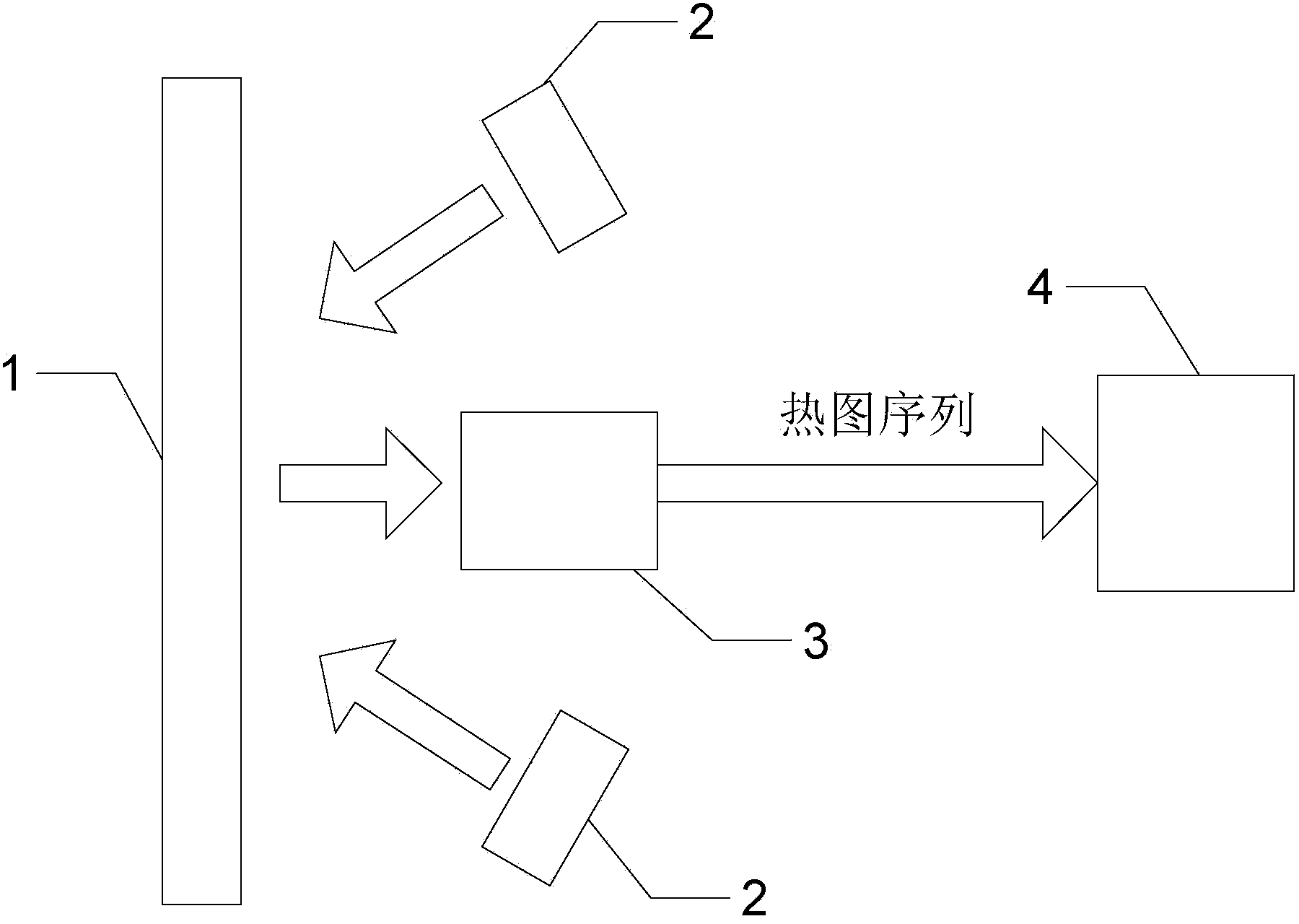
[0014] Specific implementation mode one: combine figure 1 Describe this embodiment, what is described in this embodiment,
[0015] Step 1: Using pulse heating equipment at pulse intensity Q 1 Next, the coating structural member 1 to be tested is heated, and at the same time, the infrared thermal imager 3 is used at the sampling frequency f s Next, collect the heat map sequence T of the surface of the tested coating structural member 1 1 (x, y, N), where x×y is the number of pixels of the infrared thermal imager, and N is the number of image frames collected;
[0016] Step 2: Using pulse heating equipment at pulse intensity Q 2 Next, the coating structural member 1 to be tested is heated, and at the same time, the infrared thermal imager 3 is used at the sampling frequency f s Next, collect the heat map sequence T of the surface of the tested coating structural member 1 2 (x,y,N);
[0017] Step 3: The obtained heat map sequence T 2 (x,y,N) and heatmap sequence T 1 (x, y...
specific Embodiment approach 2
[0037] Embodiment 2: This embodiment is a further limitation of the method for measuring coating thickness by optical pulse infrared thermal imaging described in Embodiment 1.
[0038] The pulse heating device is a high-energy flash lamp 2 .
specific Embodiment approach 3
[0039] Embodiment 3: This embodiment is a further limitation of the method for measuring coating thickness by optical pulse infrared thermal imaging described in Embodiment 1.
[0040] The step 3, step 4 and step 5 are all realized by software embedded in the computer 4 .
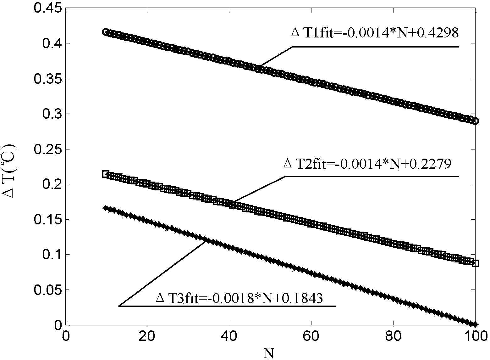
[0041] The process of measuring coating thickness by light pulse infrared thermal imaging technology will be described below in conjunction with the examples. In this embodiment, a high-temperature anti-oxidation coating / heat-resistant alloy substrate flat specimen is used, the thickness of the coating is not uniform, and the thermal diffusivity of the coating is α c =2.5×10 -9 m 2 / s. Set the sampling frequency f of the thermal imager 3 s =50Hz. Take the pulse intensity as Q 1 =7.5kW / m 2 and Q 2 =9.5kW / m 2 Perform thermal excitation on the tested part to obtain the heat map sequence T 1 (x,y,N) and T 2 (x,y,N). Will T 2 (x,y,N) and T 1 Subtract (x, y, N) to get △T(x, y, N).
[0042] figure ...
PUM
 Abstract
Description
Claims
Application Information
 - R&D
- Intellectual Property
- Life Sciences
- Materials
- Tech Scout
- Unparalleled Data Quality
- Higher Quality Content
- 60% Fewer Hallucinations
Browse by: Latest US Patents, China's latest patents, Technical Efficacy Thesaurus, Application Domain, Technology Topic, Popular Technical Reports.
© 2025 PatSnap. All rights reserved.Legal|Privacy policy|Modern Slavery Act Transparency Statement|Sitemap|About US| Contact US: help@patsnap.com


