
A method of measuring coating thickness by light pulse infrared thermal imaging

A technology of infrared thermal imaging and coating thickness, which is applied in the direction of measuring devices, optical devices, electric radiation detectors, etc., can solve problems such as limitations of material properties, and achieve the effect of simple methods and overcoming limitations

Active Publication Date: 2016-08-10
HEILONGJIANG UNIVERSITY OF SCIENCE AND TECHNOLOGY
View PDF3 Cites 2 Cited by
  • Summary
  • Abstract
  • Description
  • Claims
  • Application Information

AI Technical Summary

Problems solved by technology

[0004] The purpose of the present invention is to solve the problem that the current method of measuring coating thickness has limitations on the measured material properties. The present invention provides a method for measuring coating thickness by optical pulse infrared thermal imaging

Method used


Image

  • A method of measuring coating thickness by light pulse infrared thermal imaging
  • A method of measuring coating thickness by light pulse infrared thermal imaging
  • A method of measuring coating thickness by light pulse infrared thermal imaging

Examples


specific Embodiment approach 1

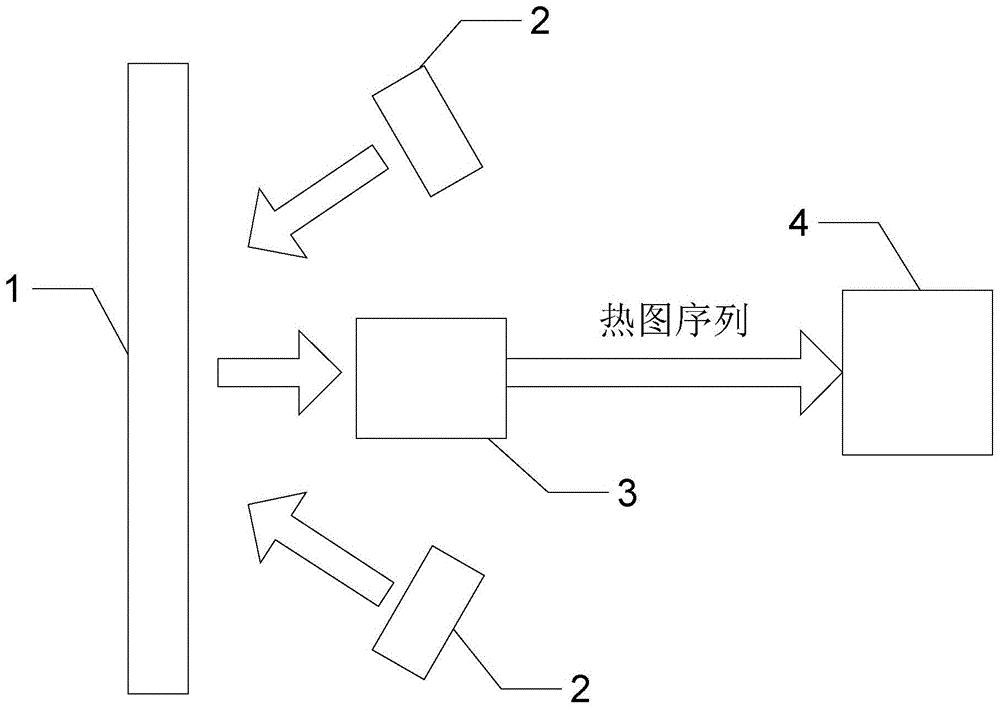
[0014] Specific implementation mode one: combine figure 1 Describe this embodiment, what is described in this embodiment,

[0015] Step 1: Using pulse heating equipment at pulse intensity Q 1 Next, the coating structural member 1 to be tested is heated, and at the same time, the infrared thermal imager 3 is used at the sampling frequency f s Next, collect the heat map sequence T of the surface of the tested coating structural member 1 1 (x, y, N), where x×y is the number of pixels of the infrared thermal imager, and N is the number of image frames collected;

[0016] Step 2: Using pulse heating equipment at pulse intensity Q 2 Next, the coating structural member 1 to be tested is heated, and at the same time, the infrared thermal imager 3 is used at the sampling frequency f s Next, collect the heat map sequence T of the surface of the tested coating structural member 1 2 (x,y,N);

[0017] Step 3: The obtained heat map sequence T 2 (x,y,N) and heatmap sequence T 1 (x, y...

specific Embodiment approach 2

[0037] Embodiment 2: This embodiment is a further limitation of the method for measuring coating thickness by optical pulse infrared thermal imaging described in Embodiment 1.

[0038] The pulse heating device is a high-energy flash lamp 2 .

specific Embodiment approach 3

[0039] Embodiment 3: This embodiment is a further limitation of the method for measuring coating thickness by optical pulse infrared thermal imaging described in Embodiment 1.

[0040] The step 3, step 4 and step 5 are all realized by software embedded in the computer 4 .

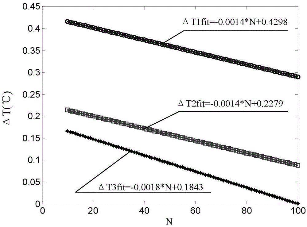
[0041] The process of measuring coating thickness by light pulse infrared thermal imaging technology will be described below in conjunction with the examples. In this embodiment, a high-temperature anti-oxidation coating / heat-resistant alloy substrate flat specimen is used, the thickness of the coating is not uniform, and the thermal diffusivity of the coating is α c =2.5×10 -9 m 2 / s. Set the sampling frequency f of the thermal imager 3 s =50Hz. Take the pulse intensity as Q 1 =7.5kW / m 2 and Q 2 =9.5kW / m 2 Perform thermal excitation on the tested part to obtain the heat map sequence T 1 (x,y,N) and T 2 (x,y,N). Will T 2 (x,y,N) and T 1 Subtract (x, y, N) to get △T(x, y, N).

[0042] figure ...


PUM


Abstract

The invention provides a method for measuring coating thickness by optical pulse infrared thermal imaging, relating to a method for measuring coating thickness. In order to solve the problem that the current method of measuring coating thickness has limitations on the measured material properties. Using pulse heating equipment to heat the tested coating structural member under two different pulse intensities, and using an infrared thermal imager at the same sampling frequency f s The thermal map sequence T of the surface of the tested coating structural member is collected as follows 1 (x,y,N) and T 2 (x, y, N); Subtract the two obtained heat map sequences to obtain the heat wave signal △T=T 2 (x,y,N)-T 1 (x, y, N); linearly fit the relationship between the thermal wave signal of all pixels and the number of acquisition frames, and get △T(x, y, N)=aN+b; according to the obtained a and b , combined with the formula Find the coating thickness e of the coating structural member under test c . It is used to measure the coating thickness of coated structural components.

Description

technical field [0001] The invention relates to a method for measuring coating thickness, in particular to a method for measuring coating thickness by optical pulse infrared thermal imaging. Background technique [0002] Pulse infrared thermal imaging technology is a non-destructive testing technology developed after the 1980s. This method is based on the thermal wave theory, by actively applying pulsed thermal excitation to the measured object, using an infrared thermal imager to continuously observe and record the temperature change on the surface of the object, and processing and analyzing the thermal wave signal through image processing technology, In order to realize the qualitative diagnosis and quantitative identification of the internal discontinuous structure of the object. [0003] At present, the method of measuring coating thickness mainly includes eddy current thickness measurement method, but this method is only suitable for the measurement of metal coating th...

Claims


Application Information

Patent Timeline
Patent Type & Authority Patents(China)
IPC IPC(8): G01B11/06G01J5/10
Inventor 唐庆菊齐立涛刘元林芦玉梅张志平
Owner HEILONGJIANG UNIVERSITY OF SCIENCE AND TECHNOLOGY
Learn More