Automatic sampler and sampling needle

A technology of automatic sampling and sampling needles, which is applied in the direction of instruments and analytical materials, can solve the problems of affecting normal sampling, large dead volume, inconvenient cleaning, etc., and achieve the goals of improving sampling accuracy, reducing cross-contamination, and high surface finish Effect

Active Publication Date: 2013-12-25
苏州理瞳精密测量系统有限公司
View PDF5 Cites 2 Cited by
  • Summary
  • Abstract
  • Description
  • Claims
  • Application Information

AI Technical Summary

Problems solved by technology

[0003] 1. The sampling needle of the back-end casing. Although the later installation and maintenance of this sampling needle is more convenient, the process of the casing is more difficult, and it is easy to generate a lot of air bubbles, which affects normal sampling.
[0004] 2. The sampling needle pipeline is directly manufactured with the sampling needle as an integral structure, which can be used for the injector of the push-in sampling method or the sampler of the sampling mechanism with the sampling needle only moving in the Z direction, and the scope of application is limited
[0005] 3. The back end of the sampling needle is connected to the pipeline through a two-way joint. Although the structure of this sampling needle is simple, the cost is relatively high;
[0006] 4. In addition, the sealing effect of the pipe fittings selected by the existing sampling needle is not ideal. The gap between the end of the pipe and the connection part of the sampling needle body is large, that is, the dead volume is large, it is not easy to clean, easy to store residues, and easy to produce Cross-contamination, affecting the accuracy of sampling

Method used


Image

  • Automatic sampler and sampling needle
  • Automatic sampler and sampling needle
  • Automatic sampler and sampling needle

Examples


Embodiment Construction

[0036] The details of the present invention can be understood more clearly with reference to the accompanying drawings and the description of specific embodiments of the present invention. However, the specific embodiments of the present invention described here are only for the purpose of explaining the present invention, and should not be construed as limiting the present invention in any way. Under the teaching of the present invention, the skilled person can conceive any possible modification based on the present invention, and these should be regarded as belonging to the scope of the present invention.

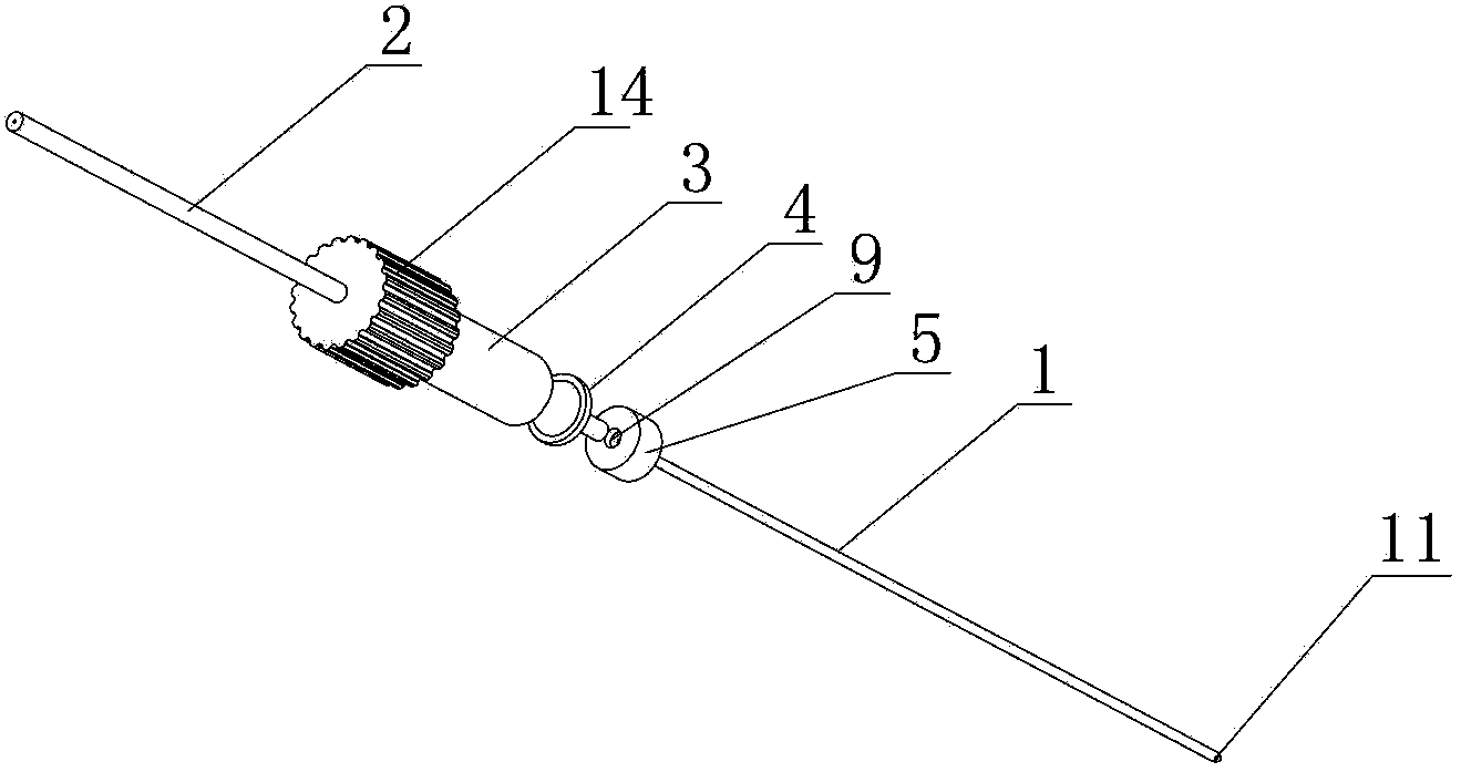
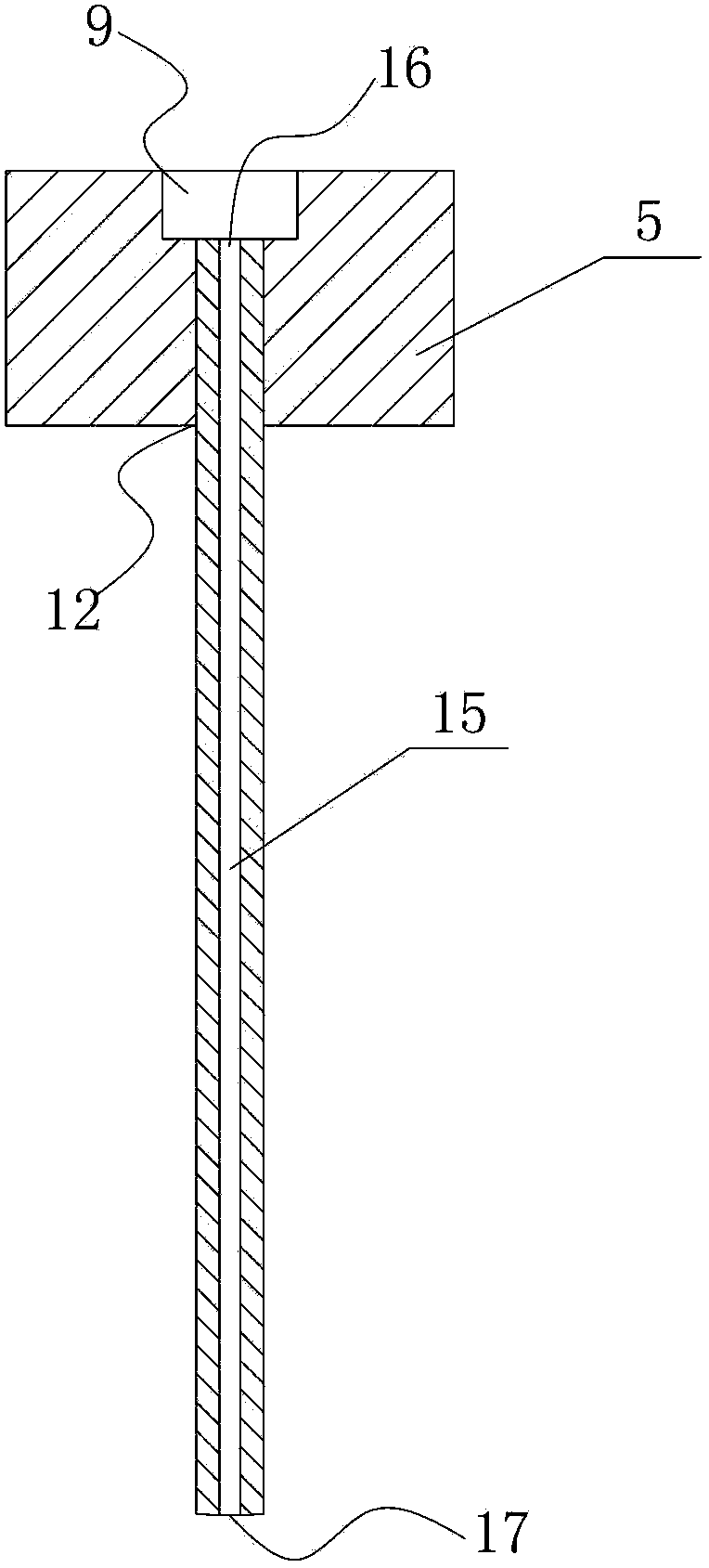
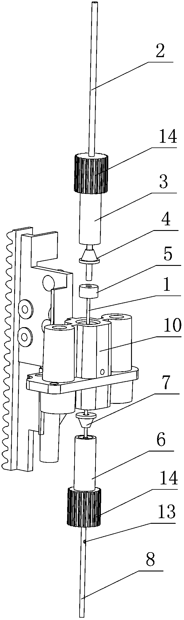
[0037] Please refer to figure 1 and Figure 4 , are respectively the structure diagram and the use state diagram of the sampling needle assembly of the autosampler of the present invention. Such as figure 1 , 4 As shown, the autosampler proposed by the present invention at least includes a sampling needle assembly, which is fixed on the upper and lower threaded mounti...


PUM


Abstract

The invention discloses an automatic sampler and a sampling needle; the automatic sampler at least comprises a sampling needle assembly; the sampling needle assembly includes the sampling needle; the upper end and the lower end of the sampling needle are respectively provided with an upper end port and a lower end port, and the lower end port of the sampling needle is a sampling hole; a cylindrical connecting head is connected to the upper end of the sampling needle, the connecting head is positioned in an upper threaded mounting hole, the center of the connecting head is provided with a mounting groove, a sampling tube is inserted into the mounting groove of the connecting head, the lower end port of the sampling tube is jointed with the bottom surface of the mounting groove and is communicated with the upper end port of the sampling needle; the lower part of the sampling tube is sleeved by an upper joint and an upper blade ring, the outer wall of the upper joint is in threaded connection with the upper part of a threaded mounting hole of a sampling needle frame; and when the upper joint drives the blade ring to be pressed tightly onto the connecting head, the lower end port of the sampling tube is pressed tightly onto the bottom surface of the mounting groove and is communicated with the upper end port of the sampling needle. The automatic sampler has the advantages of simple manufacture, low cost, high sample introduction accuracy and less cross pollution.

Description

technical field [0001] The invention relates to an automatic sample injector, in particular to a sampling needle with simple manufacture, low cost, high sampling accuracy and less cross-contamination and an automatic sample injector with the sampling needle. Background technique [0002] The sampling needle is a very critical part of the autosampler, which determines the injection accuracy and cross-contamination index of the autosampler. At present, due to the different structure of the motion mechanism of the sampling system of the sampler, the motion form of the sampling needle is also different. Generally, the sampling needle has two degrees of freedom and one degree of freedom. According to the different motion forms of the needle, the structure of the sampling needle has the following types: [0003] 1. The sampling needle of the back-end sleeve. Although the later installation and maintenance of this sampling needle is more convenient, the process of the sleeve is mo...

Claims


Application Information

Patent Timeline
Patent Type & Authority Applications(China)
IPC IPC(8): G01N35/10
Inventor 周国玲王悦王铁军李维森
Owner 苏州理瞳精密测量系统有限公司
Why Eureka
Try Eureka