
Method for realizing multi-point real touch on surface acoustic wave touch screen

A surface acoustic wave and real touch technology, applied in the input/output process of data processing, instruments, electrical digital data processing, etc., can solve problems that affect the recognition of coordinate points by the firmware system and cannot produce surface acoustic wave touch screens, etc.

Active Publication Date: 2013-12-25
GENERAL TOUCH CO LTD
View PDF6 Cites 5 Cited by
  • Summary
  • Abstract
  • Description
  • Claims
  • Application Information

AI Technical Summary

Problems solved by technology

[0010] The patent adds a Z-axis that can assist in screening ghost points. After adding the Z-axis, a maximum of two physical touch objects can be recognized at the same time, and a set of U-axis perpendicular to the Z-axis can be added, and a maximum of three physical touch objects can be recognized at the same time. , so theoretically there are N groups of coordinate axes, and N-1 physical touch objects can be identified at the same time, but increasing the number of coordinate axis groups also requires adding corresponding reflection stripe arrays around the touch screen body, and the surface acoustic wave signal passes through multiple groups of reflection stripes A lot of messy signals are generated behind the array, and the transducers are easy to be received, which seriously affects the firmware system’s recognition of coordinate points. At the same time, adding multiple sets of reflective stripe arrays requires a wider touch screen around the body to meet the spatial layout requirements of the reflective stripe array. It runs counter to the current market demand for light weight, narrower, borderless and flat touch screens, and the existing processing technology cannot produce surface acoustic wave touch screens with N sets of coordinate axes

Method used


Image

  • Method for realizing multi-point real touch on surface acoustic wave touch screen
  • Method for realizing multi-point real touch on surface acoustic wave touch screen
  • Method for realizing multi-point real touch on surface acoustic wave touch screen

Examples


Embodiment 1

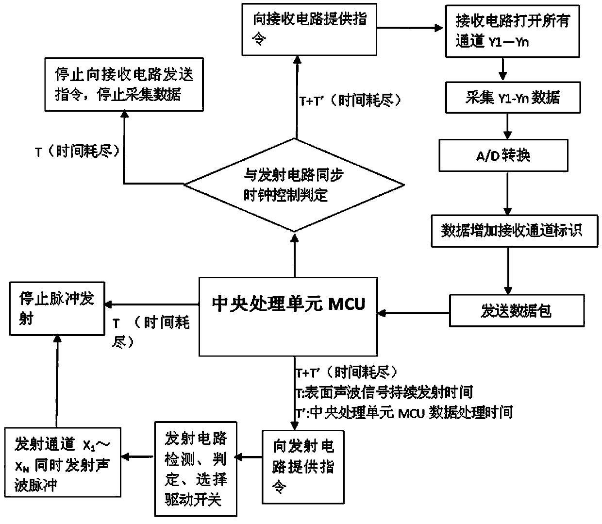
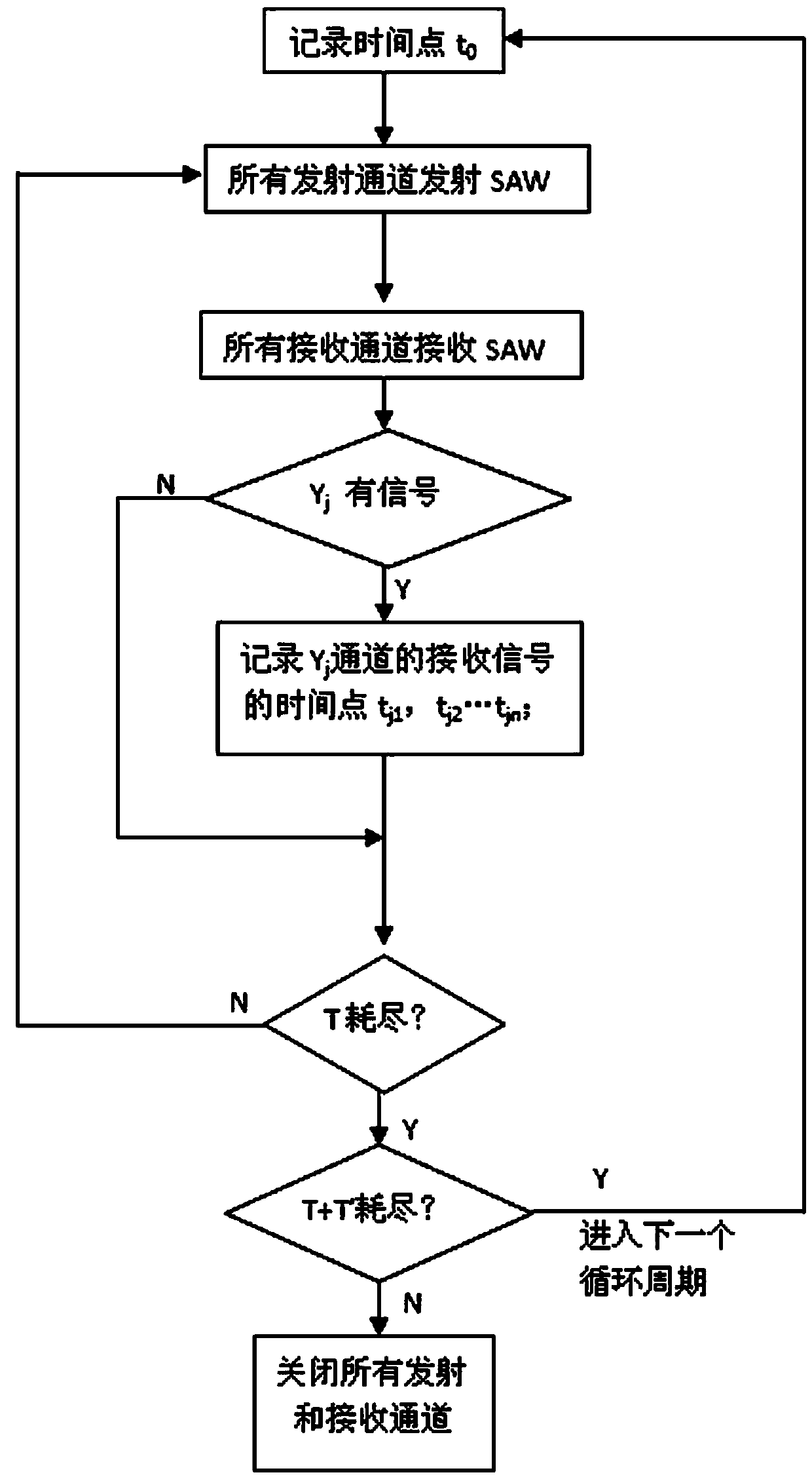
[0105] A method for realizing multi-point real touch on a surface acoustic wave touch screen, comprising the following steps:

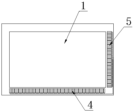
[0106] (1) Set at least one set of transmitting transducer array 4 formed by multiple transmitting transducers 6 on the X-axis or Y-axis, or at least set one set of receiving transducer arrays formed by multiple receiving transducers 2 device array 5;

[0107] (2), the transmitting transducer 6 is driven by the transmitting circuit to transmit the surface acoustic wave signal, and the receiving circuit controls the receiving transducer 2 to receive the surface acoustic wave signal;

[0108] (3) When touched by a touch object, the surface acoustic wave signal reaches the receiving transducer 2 after passing through the touch object. When the strength of the surface acoustic wave signal is greater than the set threshold, the receiving circuit sends the surface acoustic wave signal to the central processing unit MCU, the central processing unit MCU dete...

Embodiment 2

[0122] This embodiment is basically the same as Embodiment 1, the main difference is that a set of transmitting transducer arrays 4 is set on the X axis, a set of receiving transducer arrays 5 is set on the Y axis, and any transmitting transducer array 5 6, the transmitting circuit drives the transmitting transducer 6 to emit the surface acoustic wave signal in turn, until all the transmitting transducers 6 are driven once, and then ends a cycle; the receiving circuit controls all the receiving transducers 2 to receive simultaneously The surface acoustic wave signal, or all the receiving transducers 2 are controlled by the receiving circuit to receive the surface acoustic wave signal separately in turn; the above-mentioned setting method is preferred, but not limited to the above-mentioned preferred setting method, for example, a group of transmitting transducers can be set on the X axis Transducer array 4, two groups of receiving transducer arrays 5 are arranged on the Y axis....

Embodiment 3

[0133] This embodiment is basically the same as Embodiment 2, the main difference is that a group of transmitting transducer arrays 4 is arranged on the X axis, and a single receiving transducer 2 and a reflective stripe array 3 are arranged on the Y axis. Combination, starting from any transmitting transducer 6, the transmitting circuit drives the transmitting transducer 6 to emit the surface acoustic wave signal in turn, until all the transmitting transducers 6 are driven once, then ends a cycle; controlled by the receiving circuit The receiving transducer 2 receives the surface acoustic wave signal; the above-mentioned arrangement is preferred, but not limited to the above-mentioned preferred arrangement, for example, two groups of transmitting transducer arrays 4 can be respectively arranged on the two sides of the X-axis, and on the Y-axis Two combinations formed by a single receiving transducer 2 and a reflective stripe array 3 are arranged on the two sides of each.

[0...


PUM


Abstract

The invention discloses a method for realizing multi-point real touch on a surface acoustic wave touch screen. The method comprises the following steps that (1), a group of transmitting transducer arrays or receiving transducer arrays are at least arranged on the X axis or the Y axis; (2), a transmitting circuit drives transmitting transducers to transmit a surface acoustic wave signal, and a receiving circuit controls receiving transducers to receive the surface acoustic wave signal; (3), when a touch body touches the surface acoustic wave touch screen, the surface acoustic wave signal reaches the receiving transducers after being reflected by the touch body; when the surface acoustic wave signal intensity is greater than a set threshold value, the receiving circuit sends the surface acoustic wave signal to an MCU (microprocessor control unit), and the MCU determines the coordinates of the touch body. By the method, the multi-point real touch response of two or more points is realized, ghost points are eliminated fundamentally, and moreover, the touch response of unlimited points in a touch area can be really realized by the conventional process.

Description

technical field [0001] The invention relates to a surface acoustic wave touch screen, in particular to a method for realizing multi-point real touch on the surface acoustic wave touch screen. Background technique [0002] The current touch screens mainly include surface acoustic wave, infrared, and capacitive types. Among them, the surface acoustic wave touch screen has become the most popular among several mainstream touch screens due to its advantages such as high resolution, short response time, strong environmental adaptability, good stability, and good light transmission. A touch screen with promotional value. [0003] The existing ordinary surface acoustic wave touch screen only has two physical positioning axes perpendicular to each other, the X axis and the Y axis. Based on the principle of axis intersection, a touch point can be accurately identified and a unique set of position coordinate data can be obtained. However, for two or more When the touch points are ope...

Claims


Application Information

Patent Timeline
IPC IPC(8): G06F3/043
CPCG06F3/043G06F3/0433G06F2203/04104
Inventor 罗琳张萍
Owner GENERAL TOUCH CO LTD
Learn More