
Method for calibrating camera

A camera calibration and calibration object technology, which is applied in image analysis, instruments, calculations, etc., can solve problems such as unsuitable calibration, high equipment requirements, and inability to guarantee convergence

Inactive Publication Date: 2013-12-25
UNIV OF SHANGHAI FOR SCI & TECH
View PDF2 Cites 30 Cited by
  • Summary
  • Abstract
  • Description
  • Claims
  • Application Information

AI Technical Summary

Problems solved by technology

[0006] This self-calibration method has a simple algorithm and can obtain a linear solution. The disadvantage is that there must be a camera motion platform that can be precisely controlled.
The disadvantage is that the initial value of the nonlinear optimization algorithm can only be obtained through estimation, and its convergence cannot be guaranteed
[0023] The Tsai method has relatively high precision and is suitable for precision measurement, but this method cannot be calibrated to obtain some internal parameters (d x , d y , u O , v O ), and the requirements for equipment are also very high, not suitable for simple calibration

Method used


Image

  • Method for calibrating camera
  • Method for calibrating camera
  • Method for calibrating camera

Examples


Embodiment Construction

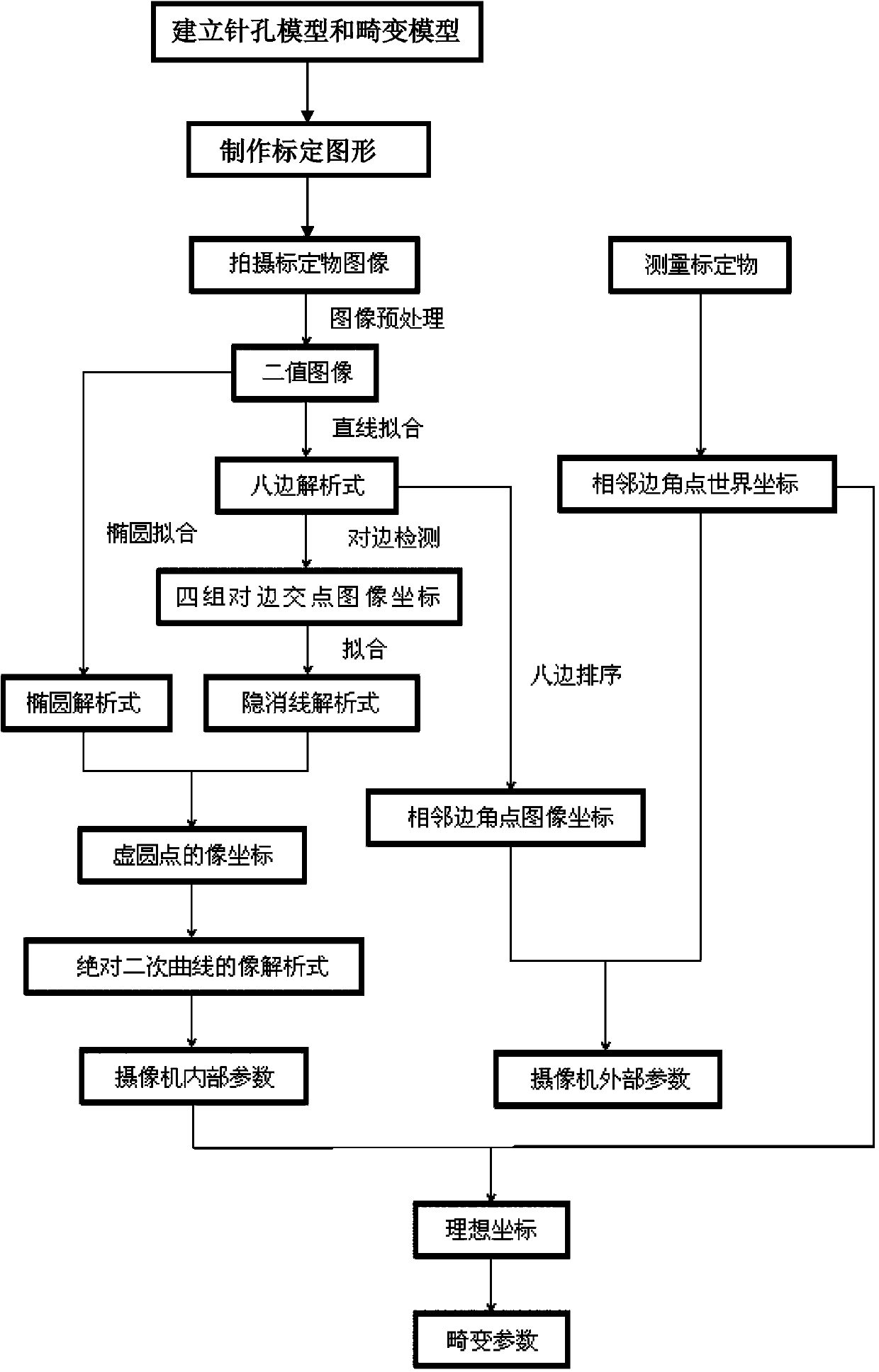
[0062] The present invention will be further described below in conjunction with the accompanying drawings and embodiments. figure 1 It is a flow chart of the specific steps of camera calibration in the embodiment of the present invention, such as figure 1 As shown, the specific steps of applying this method for camera calibration are as follows:

[0063] Step 1: Establish pinhole model and distortion model.

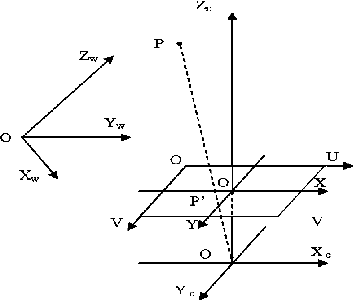
[0064] Since the camera is an optical imaging instrument that satisfies the projective characteristics, it is modeled using the pinhole model. The imaging process is essentially a coordinate transformation between four coordinate systems, which are the world coordinate system, camera coordinate system, image physical coordinate system, and image pixel coordinate system.

[0065] figure 2 is the coordinate diagram of the pinhole model in the embodiment of the present invention. Such as figure 2 As shown, the world coordinate system O-XwYwZw is established in space ...


PUM


Abstract

The invention provides a method for calibrating a camera. According to a camera calibration line circle method, a circle and an inscribed regular octagon of the circle are used as calibration objects for calibrating the camera. The circle and the inscribed regular octagon of the circle are used as the calibration objects, the camera is used for shooting the calibration objects from three different angles, three calibration object images are obtained, the calibration process is based on the shooting geometric principle, according to the relevance of the image of an absolute conic and the inside parameter of the camera, a hidden line intersects with an ellipse to obtain a circular point, an absolute conic equation is further obtained, and the inside parameter of the camber is obtained finally. An outside parameter is calibrated according to a radial array binding principle, an overdetermined equation is solved to obtain the outside parameter of the camera, at last, the radial distortion of the camera is considered, the distortion parameter of the camera is further obtained, and distortion compensation is achieved.

Description

technical field [0001] The present invention relates to a camera calibration method, in particular to a camera calibration line circle method using a circle and the inscribed regular octagon of the circle as calibration graphics to calibrate the camera Background technique [0002] One of the basic tasks of computer vision is to calculate the geometric information of the object in the three-dimensional space from the image information obtained by the camera, and then reconstruct and recognize the object, and the three-dimensional geometric position of a point on the surface of the space object and its corresponding point in the image The interrelationship of is determined by the geometric model of camera imaging, and these geometric model parameters are camera parameters. Under most conditions, these parameters must be obtained through experiments and calculations, and this process is called camera calibration (or calibration). The calibration process is to determine the ge...

Claims


Application Information

Patent Timeline
Patent Type & Authority Applications(China)
IPC IPC(8): G06T7/00
Inventor 隋国荣刘晓利田媛童飞陈培祖朱泽玮陈佳琪郑锦兴孙惠琳陆怡然
Owner UNIV OF SHANGHAI FOR SCI & TECH
Learn More