Charging device for high-power power battery pack

A technology for power battery packs and charging devices, applied in battery circuit devices, circuit devices, collectors, etc., can solve problems such as output power limitation, unbalanced power consumption, unscientific charging current, etc., to ensure balance and stability, The effect of increasing the charging speed

Active Publication Date: 2013-12-25
厦门绿洋环境技术股份有限公司
View PDF5 Cites 7 Cited by
  • Summary
  • Abstract
  • Description
  • Claims
  • Application Information

AI Technical Summary

Problems solved by technology

This kind of charging device has serious unbalanced power consumption during the charging process, and the power factor fluctuates greatly, which will seriously affect the stability of local power grid power consumption, and the output power of the single-unit charging device is generally lower than 60kW; the other is single-phase High frequency, the basic principle is: three-phase input rectified into DC → converted into AC through IGBT → single-phase high-frequency transformer → rectified into pulsating DC → added to the battery pack
Although this kind of charging device solves the three-phase balanced input of the power grid, because it still uses a single-phase high-frequency transformer, the output power is also very limited under high-frequency working conditions, generally less than 30kW, and there are different degrees of high-frequency radiation and EMC issues
[0004] 2) The charging current is unscientific, which affects the service life of the power battery

Method used


Image

  • Charging device for high-power power battery pack

Examples


Embodiment Construction

[0027] The present invention will be described in further detail below in conjunction with the accompanying drawings and specific embodiments.

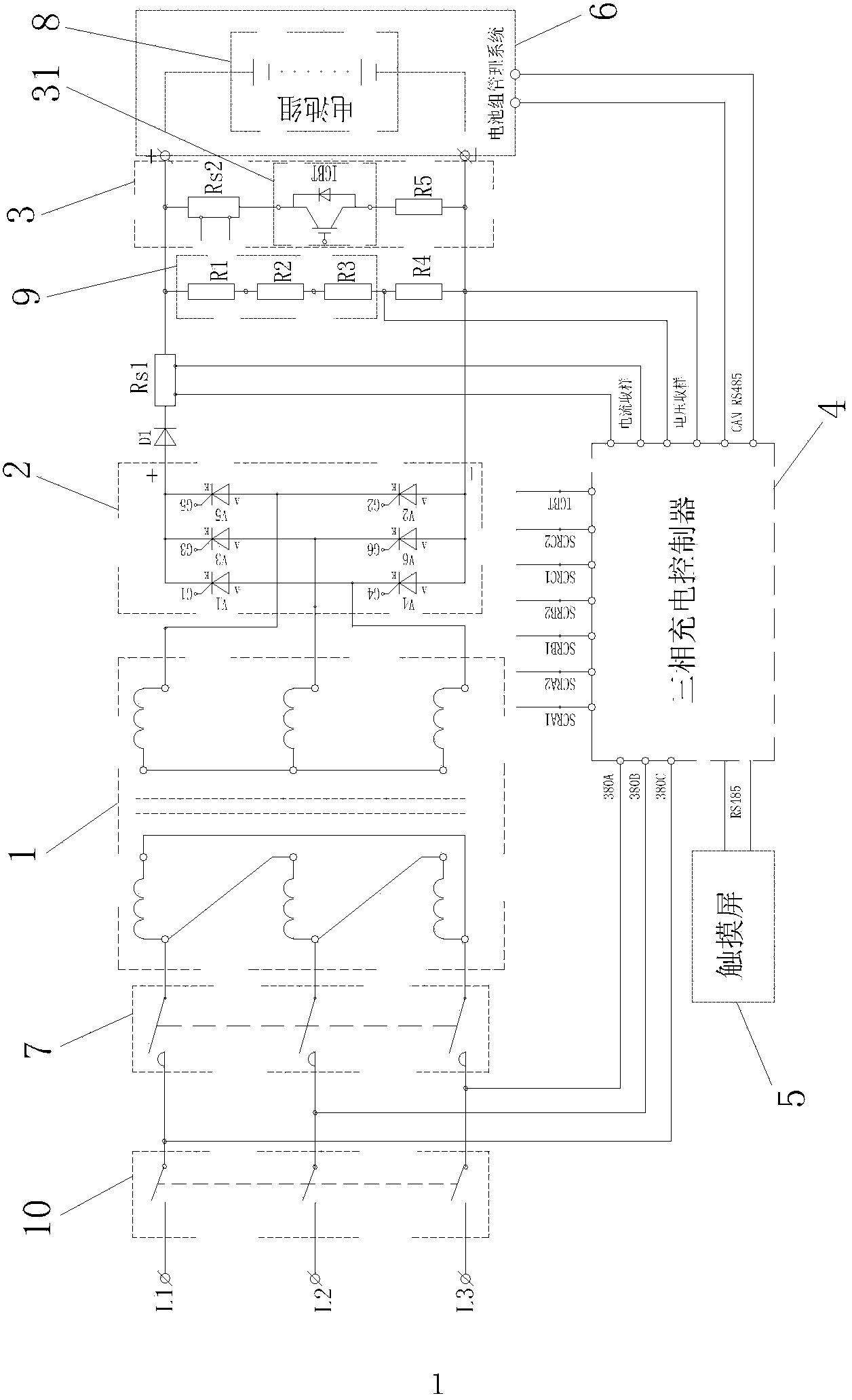
[0028] figure 1 As shown, a charging device for a high-power power battery pack includes a three-phase transformer 1, a three-phase thyristor phase-shifting voltage regulation rectifier circuit 2, an IGBT negative pulse discharge circuit 3, a three-phase charging controller 4, a touch screen 5, A battery pack management system 6, the touch screen 5 is connected to the three-phase charging controller 4 through the RS485 communication interface;

[0029] The primary coil of the three-phase transformer 1 is connected to the three-phase power supply through the contactor 7, and the three-phase thyristor phase-shift voltage regulation rectifier circuit 2 includes six thyristors, and the positive pole of the first thyristor V1 is connected to the fourth thyristor. The negative pole of the thyristor V4 is connected to the first end of the t...


PUM


Abstract

The invention discloses a charging device for a high-power power battery pack. The charging device for the high-power power battery pack comprises a three-phase transformer, a three-phase thyristor phase-shift voltage-regulating rectifying circuit, an IGBT negative-pulse discharging circuit, a three-phase charging controller and a battery pack management system, wherein a primary coil of the three-phase transformer is connected with a three-phase power source through a contactor, a secondary coil of the three-phase transformer is connected with the three-phase thyristor phase-shift voltage-regulating rectifying circuit, a secondary current and voltage sampling circuit is arranged between the three-phase thyristor phase-shift voltage-regulating rectifying circuit and the high-power power battery pack, the IGBT negative-pulse discharging circuit is arranged between the positive electrode and the negative electrode of the power battery pack in parallel, the battery pack management system is used for collecting voltage signals and temperature signals of batteries of the power battery pack, the three-phase charging controller is used for controlling the contactor, the three-phase thyristor phase-shift voltage-regulating rectifying circuit and the IGBT negative-pulse discharging circuit to carry out continuous charging or combination charging between intermittent pulse charging and negative-pulse discharging on the power battery pack according to current signals and voltage signals collected by the secondary current and voltage sampling circuit, and the voltage signals and the temperature signals of the batteries. The charging device for the high-power power battery pack is high in output power and rapid in charging, and the service life of the batteries can be prolonged.

Description

technical field [0001] The invention relates to a charging device for a power battery pack, in particular to a charging device for a high-power power battery pack. Background technique [0002] According to the research and analysis of the Chinese Academy of Sciences, in the smog event last year, hydrocarbon organic particles from the exhaust of fuel vehicles accounted for 18%. Controlling smog has become a national strategy and a hot issue in the whole society. Vehicle exhaust emissions have become the main cause of urban pollutants. one. The electric vehicle with power battery as the new energy has opened up a new field of zero emission. It has become an important technical indicator for the rapid development of electric vehicles, in which the charging device plays a key role. There are two main problems in the existing charging device: [0003] 1) The output power is small and the charging speed is slow, which cannot meet the fast charging requirements of 2C or 4C elec...

Claims


Application Information

Patent Timeline
Patent Type & Authority Applications(China)
IPC IPC(8): H02J7/04H02J7/10
Inventor 谢友金柯岚谢捷传陈清春谢友煌
Owner 厦门绿洋环境技术股份有限公司
Why Eureka
Try Eureka