Heat exchange pipe and manufacturing method thereof
A heat exchange tube and outer tube technology, applied in the field of heat exchange tubes and their manufacturing, can solve the problems of insufficient thermal contact, monotonous fluid flow, etc., and achieve the effects of easy manufacturing, improved contact performance and sealing performance, and close contact.
- Summary
- Abstract
- Description
- Claims
- Application Information
AI Technical Summary
Problems solved by technology
Method used
Image

Examples
Embodiment Construction
[0030] Hereinafter, referring to the accompanying drawings, the heat exchange tube and its manufacturing method of the present invention will be described in detail in conjunction with the correct embodiments.
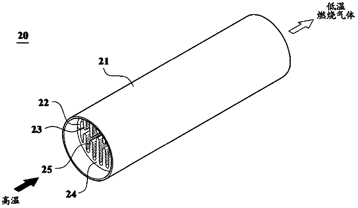
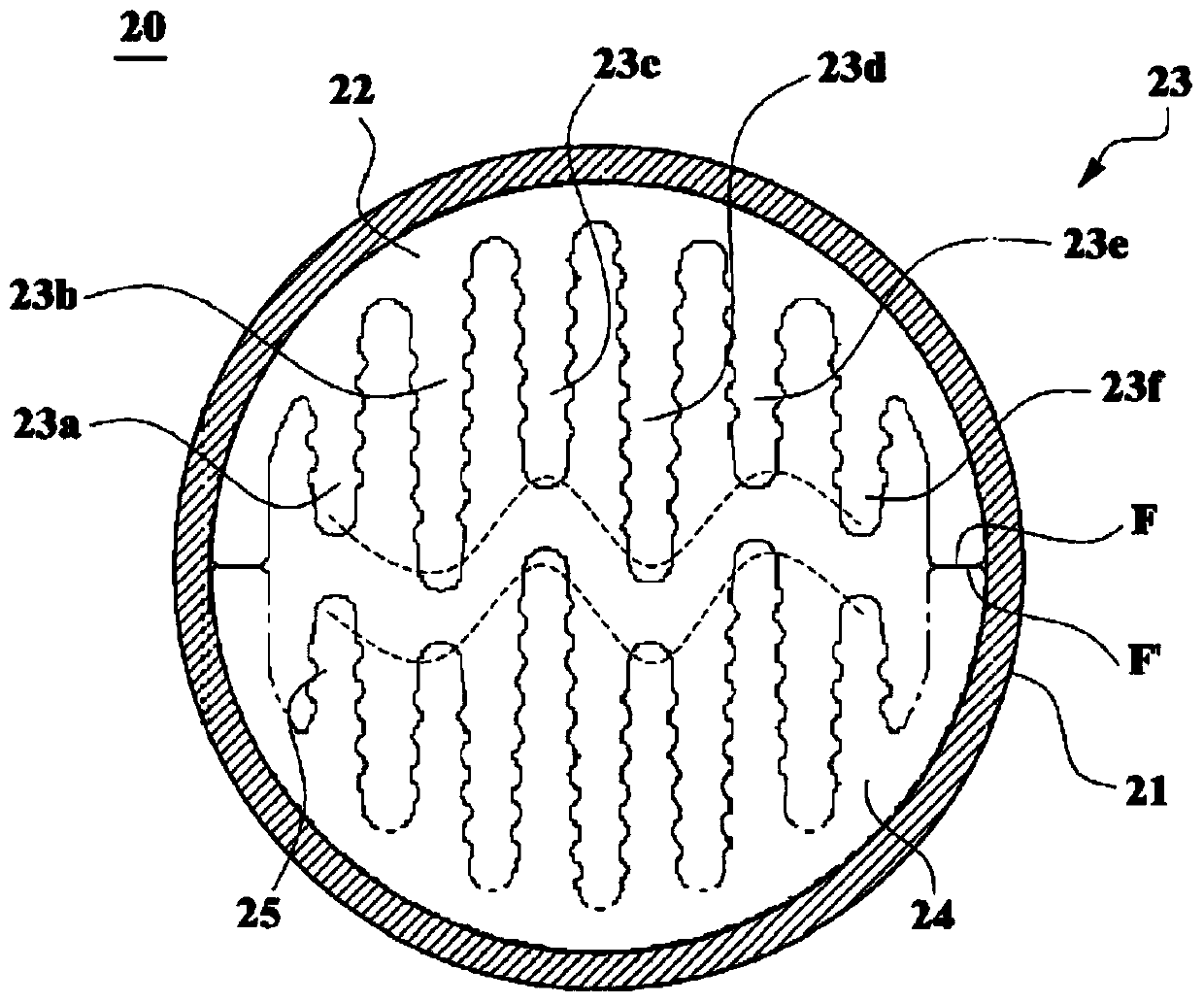
[0031] First, if figure 2 oblique view and image 3 As shown in the cross-sectional view, the heat exchange tube (20) in Example 1 consists of a cylindrical outer pipe (21) and a first half-insert (22, 23) inserted inside the outer pipe (21) and the second half-insert (24,25). In this example, the outer tube (21) is made of a metal material like steel and the first half-inserts (22,23) and second half-inserts (24,25) are made of aluminium.
[0032] At this time, the first half insert (22, 23) consists of a semicylinder first half shell cut along the vertical direction of the cylinder and a plurality of long needle-shaped first ribs (rib) (23). Similarly, the second half-insert (24, 25) is also composed of the second half-shell (24) and a plurality of second ribs (...
PUM
 Abstract
Description
Claims
Application Information
 - Generate Ideas
- Intellectual Property
- Life Sciences
- Materials
- Tech Scout
- Unparalleled Data Quality
- Higher Quality Content
- 60% Fewer Hallucinations
Browse by: Latest US Patents, China's latest patents, Technical Efficacy Thesaurus, Application Domain, Technology Topic, Popular Technical Reports.
© 2025 PatSnap. All rights reserved.Legal|Privacy policy|Modern Slavery Act Transparency Statement|Sitemap|About US| Contact US: help@patsnap.com