
Dust collector for energy-saving environment-friendly axial flow fan group

An energy-saving and environmental protection, dust removal device technology, applied in the direction of dispersed particle separation, chemical instruments and methods, dispersed particle filtration, etc., can solve the problems that the dust removal device cannot achieve the dust removal effect, cannot reach the ecological city, and increase equipment investment. Achieve the effect of reducing power, saving resources and energy consumption, and reducing energy consumption

Inactive Publication Date: 2014-01-01
张建美
View PDF4 Cites 6 Cited by
  • Summary
  • Abstract
  • Description
  • Claims
  • Application Information

AI Technical Summary

Problems solved by technology

The traditional pulse dust removal requires auxiliary facilities such as air compressors, air storage tanks, pulse valves, etc., which not only increases the investment in equipment but also increases energy consumption, and the power of the air compressor is 8% of the total power of the entire dust removal part. ~30%, so some existing dust removal devices are far from the dust removal effect required by the national standard, let alone the standard required by the ecological city

Method used


Image

  • Dust collector for energy-saving environment-friendly axial flow fan group
  • Dust collector for energy-saving environment-friendly axial flow fan group
  • Dust collector for energy-saving environment-friendly axial flow fan group

Examples


Embodiment Construction

[0011] Embodiments of the present invention will be further described below in conjunction with the accompanying drawings.

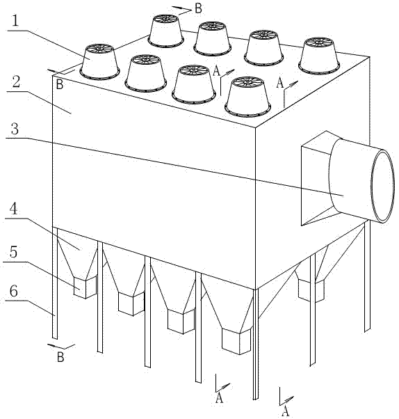
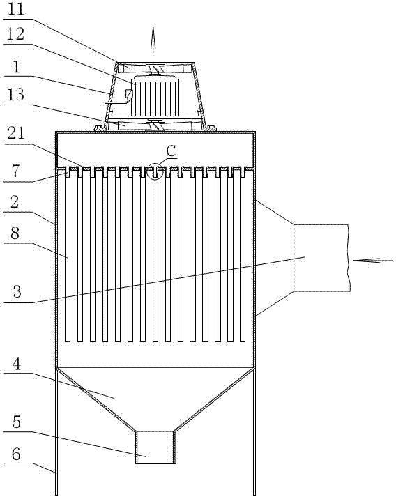
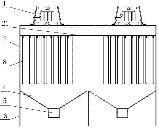
[0012] The box body 2 is a complete large cavity, which is simple in structure and easy to manufacture and process. Above the partition is a clean room and an exhaust duct, and below the partition is a dust removal room. The box is fixed on the ground through the support frames 6 at its lower end. superior.

[0013] There are eight air outlets evenly distributed on the upper surface of the box, and a fan is fixed with screws at each air outlet. On the side wall of the box 2, an air inlet pipe 3 is welded and fixed between the two symmetrical air outlets. It directly leads into the large cavity of the box body 2, and welds and fixes a partition plate 21 with a through hole at a distance of 1 to 3 meters from the top of the box body. A filter bag ring 7 is installed at the through hole of the partition plate corresponding to each fan. The port has a flang...


PUM


Abstract

A dust collector for an energy-saving environment-friendly axial flow fan group. A sidewall of a casing is equipped with an air-supply pipe, which directly penetrates into the casing; more than two air outlets are arranged on the end face of the casing; each air outlet is installed with an axial flow fan; the rotating shaft of each axial flow fan is provided with more than one impellers for generating high pressure effect through progressive increase of wind pressure of the fan; filter bags are arranged opposite to corresponding axial flow fans; the upper end of each filter bag is fixed on a separator plate with through holes in the casing; a dust bucket and a dust box are arranged below the filter bags corresponding to each axial flow fan; the separator plate and the air outlet keep a distance of 1-3 m, and the space above the separator plate forms a cleaning chamber; each axial flow fan runs in a process of forward rotation, stop, reverse rotation, stop and forward rotation; and the axial flow fans carry out cycling air-discharge and dedusting procedure in turns. The forward rotation induces air to dedust, the reverse rotation conducts back flushing ash removal with large air quantity, so as to substantially reduce filtering resistance and maintain the dust thickness in the filter bags within 0.5 mm for a long time, reduce power consumption for dedusting, thoroughly omit auxiliary facilities including a high pressure recoil pipe, a gas tank, a pulse valve and an air compressor, and realize a total energy saving of 70-80%.

Description

technical field [0001] The invention relates to a dust removal device, in particular to an energy-saving and environment-friendly axial flow fan unit dust removal device widely used in metallurgy, chemical industry, steel, thermal power plants, cement, coking, chemical fertilizer, glass factories and other large energy-consuming industries. Background technique [0002] With the strengthening of people's awareness of environmental protection, people hope to improve air quality and reduce the emission of air pollutants and haze weather. For this reason, the Ministry of Environmental Protection of the People's Republic of China has formulated emission standards for each pollutant emission unit, and also requires the implementation of rectification within a time limit. [0003] Fans and dust collectors are essential components for the implementation of pollution control projects, but traditional dust removal fans are mostly centrifugal fans, which cannot produce high-pressure ef...

Claims


Application Information

Patent Timeline
Patent Type & Authority Applications(China)
IPC IPC(8): B01D46/02B01D46/04B01D46/42
Inventor 张建美吴一中
Owner 张建美
Learn More