Modularized extrusion molding apparatus and method for section bar with order-variable cross sections

A technology of extrusion forming and cross-section, which is applied in the direction of metal extrusion dies, metal extrusion mandrels, etc., can solve the problems of difficult production of special-shaped cross-section profiles, difficult quality control, and many procedures required, and achieves easy implementation, The effect of simple equipment and short cycle

Active Publication Date: 2014-01-01
福建祥鑫股份有限公司
View PDF4 Cites 16 Cited by
  • Summary
  • Abstract
  • Description
  • Claims
  • Application Information

AI Technical Summary

Problems solved by technology

[0007] The purpose of the present invention is to provide a step-variable cross-section modular extrusion forming device and method to solve the current bottleneck problems such as difficult production of special-shaped cross-section profiles, numerous processes required, high process requirements, and difficult quality control.

Method used


Image

  • Modularized extrusion molding apparatus and method for section bar with order-variable cross sections
  • Modularized extrusion molding apparatus and method for section bar with order-variable cross sections
  • Modularized extrusion molding apparatus and method for section bar with order-variable cross sections

Examples


specific Embodiment approach 1

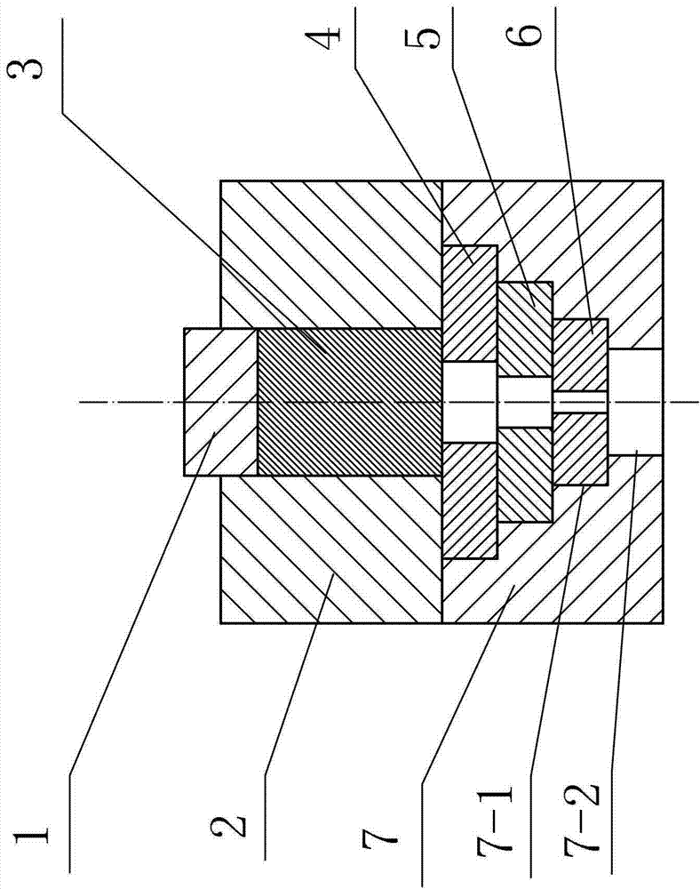
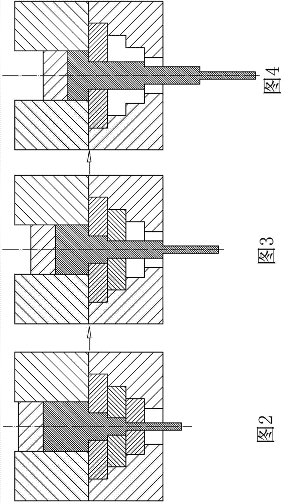
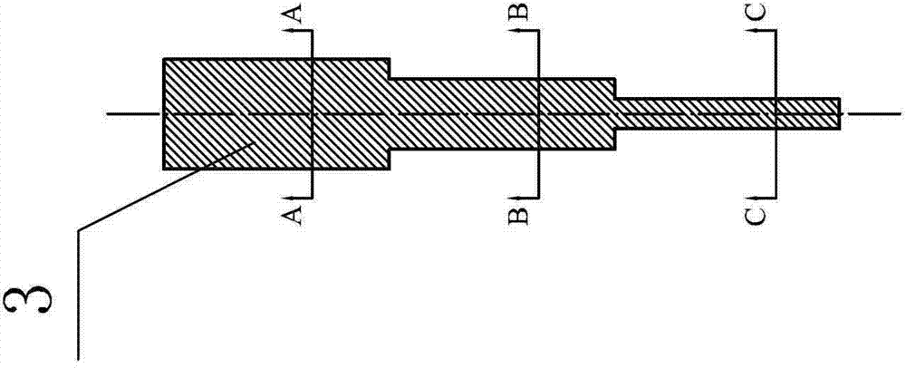
[0016] Specific implementation mode one: as figure 1 As shown, 1. A modular extrusion forming device for step-variable cross-section profiles in this embodiment is characterized in that: the extrusion forming device includes a punch 1, an extrusion cylinder 2, a base 7 and at least two module (mandrel); the base 7 has a module groove 7-1 along its length direction, and the bottom of the module groove 7-1 has a discharge through hole 7-2; the at least two modules are installed in sequence from bottom to top In the module groove 7-1 of the base 7 (that is, the at least two modules are stacked), and the uppermost module is flush with the upper end surface of the base 7, each module is formed with a die opening, and the inner diameter of each die opening is determined by From bottom to top, the die mouth of each module is set coaxially and forms a stepped hole-shaped cavity (variable cross-section cavity or axial step-shaped extrusion mold cavity); the die mouth of the module at t...

specific Embodiment approach 2

[0017] Specific implementation mode two: as figure 1 As shown, the groove surfaces on both sides of the module groove 7-1 in this embodiment are in a symmetrical step shape, and the cross-sections of each module that are parallel to the cross-section of the module groove 7-1 become larger from bottom to top, and from bottom to top The stacked module groups installed in the module groove 7-1 are matched with the module groove 7-1, and each module is installed on the shoulder surface of the corresponding position. Other components and connections are the same as those in the first embodiment.

specific Embodiment approach 3

[0018] Specific implementation mode three: as figure 1 , Figure 7 ~ Figure 9 As shown, in this embodiment, each module is formed by pairing two split molds together. One split mold can be pulled out or advanced from the notch at one end of the module groove 7-1, and the other split mold can be Pull out or advance from the other end of the module slot 7-1. Other components and connections are the same as those in the second embodiment.


PUM


Abstract

The invention provides a modularized extrusion molding apparatus and a modularized extrusion molding method for a section bar with order-variable cross sections, belonging to the field of extrusion processing technology. The invention overcomes the problems of numerous procedures, high process requirements, a substantial texture tendency and difficult implementation of conventional preparation methods for bars with different cross sections and defects like easy generation of folds and superposition of material interfaces, etc. during processing and preparation. The cavity of a first-order module, the cavity of a second-order module and the cavity of a third-order module of the apparatus are combined and form an axial step-like extrusion die cavity with a continuous order-variable surface. The method comprises the following steps: assembling the apparatus; and placing a blank material in an extrusion cylinder, putting in a punch, allowing the punch to descend so as to extrude the blank material from the die orifice of the first-order module, the die orifice of the second-order module and the die orifice of the third-order module, stopping descending of the punch, removing the third-order module, allowing the punch to go a distance downwardly, then stopping descending of the punch, removing the second-order module and allowing the punch to descend again so as to realize extrusion molding of the blank material. The invention has the following beneficial effects: the apparatus is simple, the number of production procedures is small, and the method can be easily implemented, popularized and applied in production.

Description

technical field [0001] The invention relates to a modular extrusion forming device and method for step-variable cross-section profiles, a device and a method for forming solid profiles with different cross-sections, and belongs to the technical field of extrusion processing. Background technique [0002] Aerospace vehicles, transportation equipment, etc. are products that consume a lot of energy and resources, affect the environment, and require huge infrastructure support. Their development is facing huge challenges from energy, environmental protection, and safety. In the long run, lightweight is one of the main ways to achieve energy saving and emission reduction, which not only endows parts with complex geometric features but also enables them to achieve high performance. There are two main ways to realize the lightweight structure: one is the structural way, which adopts the variable cross-section components of "replacing the solid with space", which not only reduces th...

Claims


Application Information

Patent Timeline
Patent Type & Authority Applications(China)
IPC IPC(8): B21C25/08B21C23/18
Inventor 李峰林俊峰石玮秦明汉曾祥
Owner 福建祥鑫股份有限公司
Why Eureka
Try Eureka