Automatic ultrasonic truing processing machine for wire-drawing die and processing method
A wire drawing die and processing machine technology, applied in the field of ultrasonic shaping and polishing, can solve problems such as poor stability and low production efficiency, achieve the effects of improving quality and service life, simplifying production and processing procedures, and filling technical gaps
- Summary
- Abstract
- Description
- Claims
- Application Information
AI Technical Summary
Problems solved by technology
Method used
Image
Examples
Embodiment 1
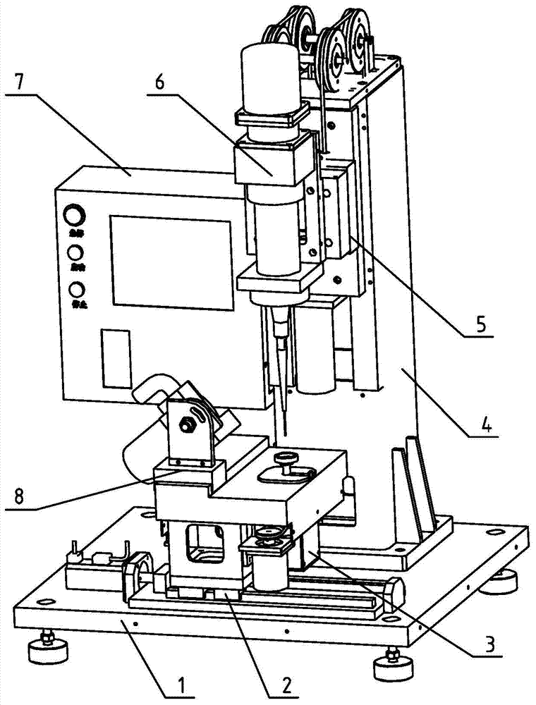
[0018] Example 1: Such as figure 1 , An automatic ultrasonic shaping machine for drawing die, its main mechanism includes: base 1, X-axis translation mechanism 2, table pressure control mechanism 3, column 4, Z-axis lifting mechanism 5, ultrasonic transducer rotating mechanism 6, control System component box 7, grinding wheel rotating reciprocating mechanism 8;
[0019] The column 4 and the X-axis translation mechanism 2 are fixed on the base 1 by screws;
[0020] The X-axis translation mechanism 2 and the Z-axis lifting mechanism 5 are respectively composed of a guide rail, a lead screw, a moving platform mechanical part and a servo motor, and the Z-axis lifting mechanism 5 is installed directly in front of the column 4;
[0021] The ultrasonic transducer rotating mechanism 6 is installed on the lifting platform of the Z-axis lifting mechanism 5 through an adapter block;
[0022] The grinding wheel rotating and reciprocating movement mechanism 8 and the table pressure control mechani...
Embodiment 2
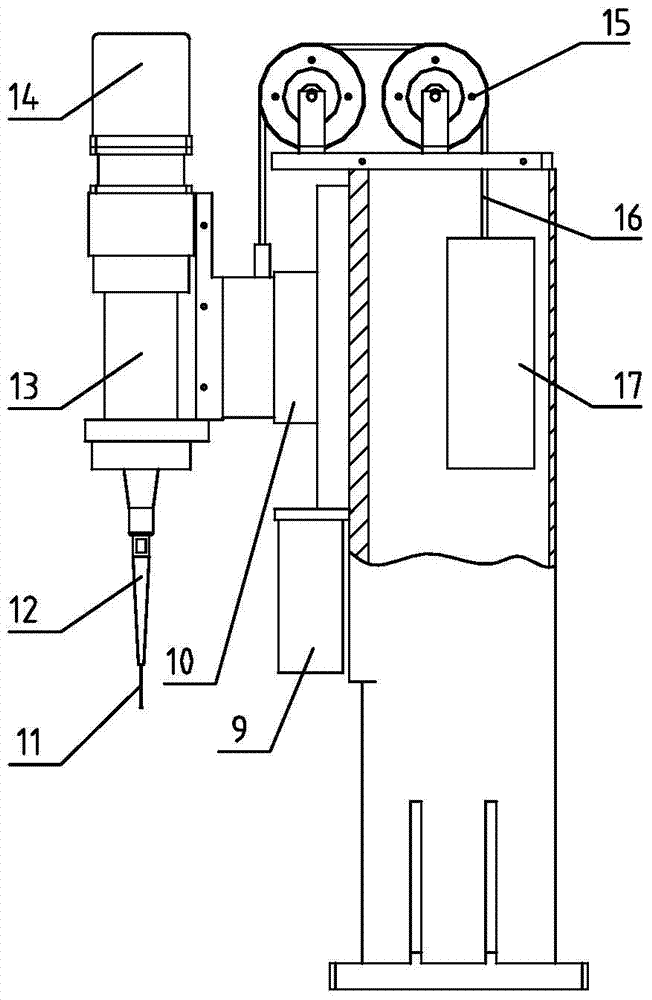
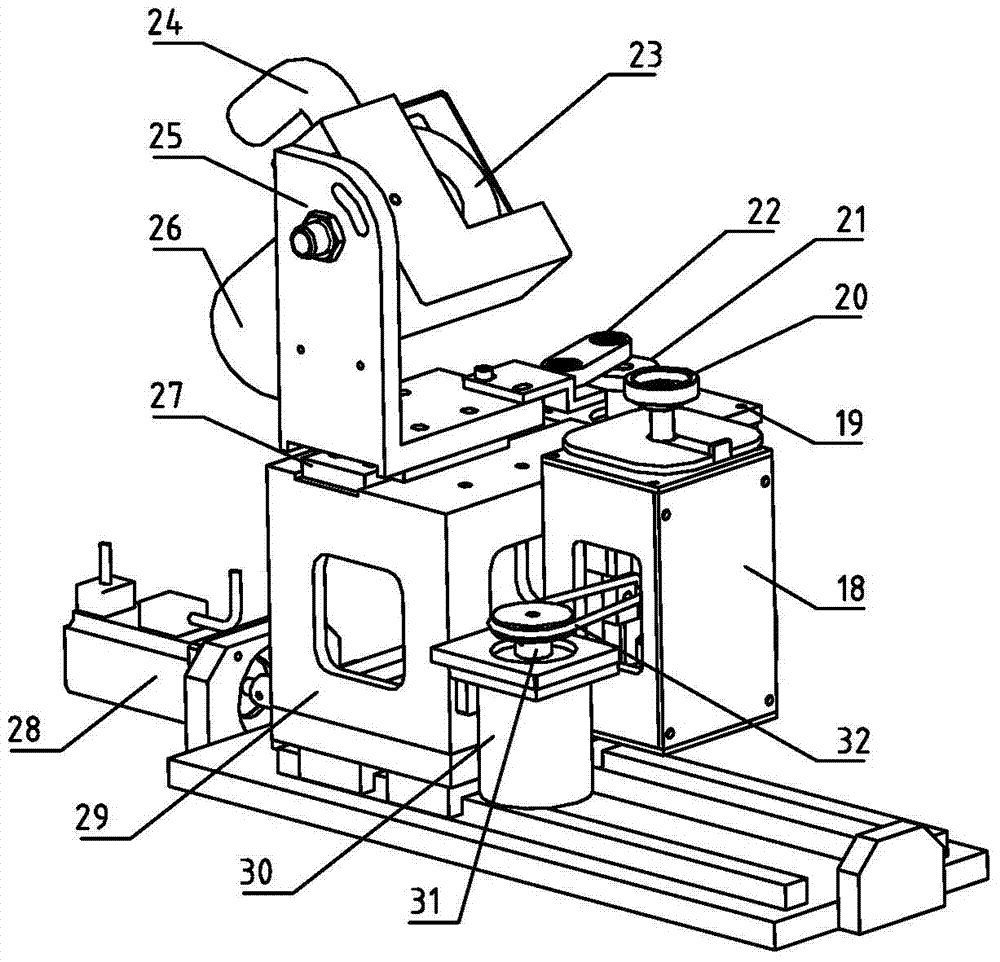
[0024] Example 2: Such as figure 1 , figure 2 , image 3 with Figure 4 As shown, an automatic ultrasonic shaping machine for drawing die, the main structure includes base 1, X-axis translation mechanism 2, table pressure control mechanism 3, column 4, Z-axis lifting mechanism 5, ultrasonic transducer rotating mechanism 6, control System component box 7, grinding wheel rotating reciprocating mechanism 8;
[0025] An automatic ultrasonic shaping machine for drawing die, its detailed structure includes Z-axis servo motor 9, Z-axis lifting table 10, ultrasonic tool needle 11, vibration transmission rod 12, ultrasonic transducer component 13, ultrasonic transducer rotating motor 14 , The first support pulley 15, the wire rope 16, the counterweight 17, the pressure sensing device 18, the grinding wheel reciprocating motor 19, the mold seat table 20, the grinding wheel reciprocating motor wheel 21, the grinding wheel reciprocating movement connecting rod 22, the grinding wheel 23, the...
Embodiment 3
[0030] Example 3: An automatic ultrasonic shaping machine for drawing die, refer to figure 1 , Which shows an axonometric view of the automatic ultrasonic shaping machine for drawing die according to an embodiment of the present invention. As can be seen from the figure, it mainly includes a base 1, an X-axis translation mechanism 2, a table pressure control mechanism 3, a column 4, and a Z-axis lift Mechanism 5, ultrasonic transducer rotating mechanism 6, control system component box 7, grinding wheel rotating and reciprocating mechanism 8. The column 4 and the X-axis translation mechanism 2 are directly installed on the base 1. The components on the translation table of the X-axis translation mechanism 2 can move left and right on the horizontal plane; the Z-axis lifting mechanism 5 is installed on the front of the column 4, and the ultrasonic transducer rotates The mechanism 6 is installed on the moving platform of the Z-axis lifting mechanism 5 and can move up and down accor...
PUM
 Abstract
Description
Claims
Application Information
 - R&D
- Intellectual Property
- Life Sciences
- Materials
- Tech Scout
- Unparalleled Data Quality
- Higher Quality Content
- 60% Fewer Hallucinations
Browse by: Latest US Patents, China's latest patents, Technical Efficacy Thesaurus, Application Domain, Technology Topic, Popular Technical Reports.
© 2025 PatSnap. All rights reserved.Legal|Privacy policy|Modern Slavery Act Transparency Statement|Sitemap|About US| Contact US: help@patsnap.com


