Epoxy resin vacuum pouring mechanical arm

A technology of vacuum casting and epoxy resin, which is applied in the field of epoxy resin casting, which can solve the problems of large volume of pouring box, low work efficiency, waste of materials, etc., and achieve the effect of small volume of vacuum box, high work efficiency and long service life

Active Publication Date: 2014-01-01
XIAMEN INSVAC MACHINERY MFG
View PDF5 Cites 5 Cited by
  • Summary
  • Abstract
  • Description
  • Claims
  • Application Information

AI Technical Summary

Problems solved by technology

[0005] 1. Since the material guide groove is open, during the pouring process, especially when the flow rate of the material in the pouring pipe is high, the material is easy to splash, waste material, pollute the internal environment of the vacuum pouring box, and may affect the pouring product due to the splash of material the quality of;
[0006] 2. In the process of switching the pouring station, although the inlet valve is closed, there is still a lot of material left in the feed pipe and feed trough, which will be poured to the outside or edge of the mold during the switch station process, which will also cause material waste, Environmental pollution and product quality are easily affected;
[0007] 3. The product placement area is only a square area of ​​a×a, the amount of pouring products in each working cycle is small, and the work efficiency is low;
[0008] 4. The length dimension L of the inner cavity of the switching pouring box must be greater than 2a. The volume of the pouring box is large, and it takes a long time to vacuumize, which affects work efficiency and does not save energy. At the same time, the pouring box occupies a relatively large area;
[0009] 5. This pouring method needs to manually press the button switch to control the start and stop of the pouring mechanism and the drive motor of the product trolley to switch the pouring station, and the work efficiency is low.

Method used


Image

  • Epoxy resin vacuum pouring mechanical arm
  • Epoxy resin vacuum pouring mechanical arm
  • Epoxy resin vacuum pouring mechanical arm

Examples


Embodiment Construction

[0028] The present invention will be further described below in conjunction with the accompanying drawings and specific embodiments.

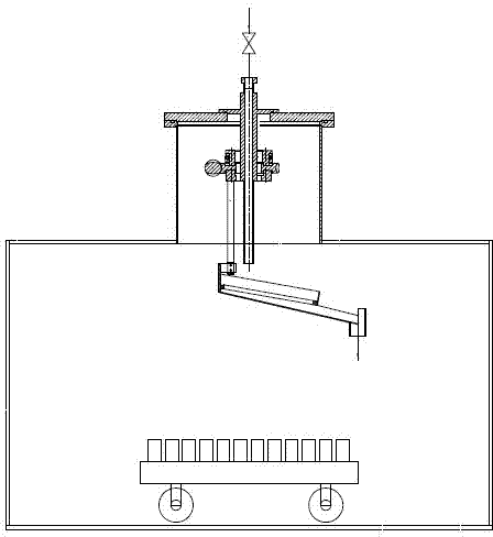
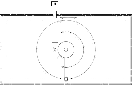
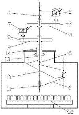
[0029] image 3 , Figure 4 , Figure 5 An epoxy resin vacuum casting mechanical arm is shown, including a feed valve 1, a feed pipe, a spindle drive servo reduction motor 2, a spindle drive pinion 3, a spindle gear 4, a pouring main arm 5, a pouring forearm 6, and a forearm Swing drive servo deceleration motor 7, forearm drive pinion 8, forearm swing gear 9, forearm swing push rod 10, pouring angle valve 11, shaft sleeve 13 and sealing chamber 14, feed valve 1 is at one end of feed pipe, feed The feeding tube passes through the main shaft gear 4, the feeding tube is connected to the casting main arm 5 through the rotary joint, the casting main arm 5 passes through the forearm swinging gear 9 and is fixed on the vacuum sealed box through the sealing chamber 14 and the shaft sleeve 13, and the casting The main arm 5 is connected to the castin...


PUM


Abstract

The invention relates to an epoxy resin vacuum pouring mechanical arm. The epoxy resin vacuum pouring mechanical arm comprises a vacuum pouring box, a feeding part, a driving part, a sealing part and a pouring part, wherein the feeding part comprises a feeding valve and a feeding pipe, the feeding pipe is connected with the pouring part by a rotary joint, the pouring part is fixed on the vacuum pouring box through a sealing chamber and a shaft sleeve in a sealing manner, the driving part drives the rotary joint and the shaft sleeve to rotate to drive the pouring part to move, the pouring part comprises a front pouring arm, a main pouring arm and a pouring angle valve, the front pouring arm and the main pouring arm are connected by the rotary joint, and the pouring angle valve is positioned at the tail end of the front pouring arm. When the above technical scheme is adopted, the pouring gate coverage area is greatly increased, the quantity of the poured products in each working period can be increased, the volume of the vacuum pouring box is relatively small, the vacuumizing time is short, the working efficiency is high and the energy consumption is low.

Description

technical field [0001] The invention relates to the field of epoxy resin pouring, in particular to an epoxy resin vacuum pouring mechanical arm. Background technique [0002] figure 1 The rotary casting mechanism used on the vacuum casting box in the field of vacuum casting of epoxy resin is shown, including inlet valve, material guide pipe, slewing bearing sleeve, wear ring, wear ring mounting seat, worm, worm wheel, sealing seat, Mechanical seal dynamic ring seat, guide groove, product trolley. When pouring, the inlet valve is opened, and the material is poured into the guide trough through the guide pipe, and then poured into the product mold cavity below through the pouring port at the end of the guide trough; if it needs to be transferred to the next station for pouring, the inlet valve Closed, the worm drives the worm wheel to rotate, the material guide groove rotates, and the pouring port of the material guide groove is transferred to the next station. [0003]...

Claims


Application Information

Patent Timeline
Patent Type & Authority Applications(China)
IPC IPC(8): B29C39/24
Inventor 郑森辉
Owner XIAMEN INSVAC MACHINERY MFG
Why Eureka
Try Eureka