
Polysilicon Deposition Device

A deposition device, polysilicon technology, applied in the direction of silicon compounds, inorganic chemistry, non-metallic elements, etc., can solve the problems of reducing polysilicon production output, quality decline, process cycle time increase, etc., to shorten equipment cleaning or cleaning time, improve product quality Yield, the effect of shortening the process cycle

Inactive Publication Date: 2016-01-06
SEMIMATERIALS
View PDF3 Cites 0 Cited by
  • Summary
  • Abstract
  • Description
  • Claims
  • Application Information

AI Technical Summary

Problems solved by technology

[0006] However, the technical configuration and features disclosed in the prior literatures are composed of rods and a plurality of oil jackets that respectively surround and cool the rods. Therefore, when polysilicon deposition is completed on the outer surface of each rod, it is necessary to separate the rods. The oil jacket, which has the problem of increased process cycle time
[0007] In addition, the rods disclosed in the existing prior literature have parts exposed outside the oil jacket, so a large amount of silicon powder may be generated due to the radiant heat between a pair of rods, so there is a possibility that a large amount of silicon powder will be generated, resulting in a decrease in quality, etc., which will reduce the production of polysilicon. Yield problem

Method used


Image

  • Polysilicon Deposition Device
  • Polysilicon Deposition Device
  • Polysilicon Deposition Device

Examples


no. 1 example

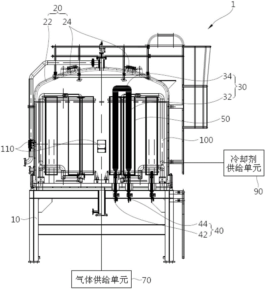
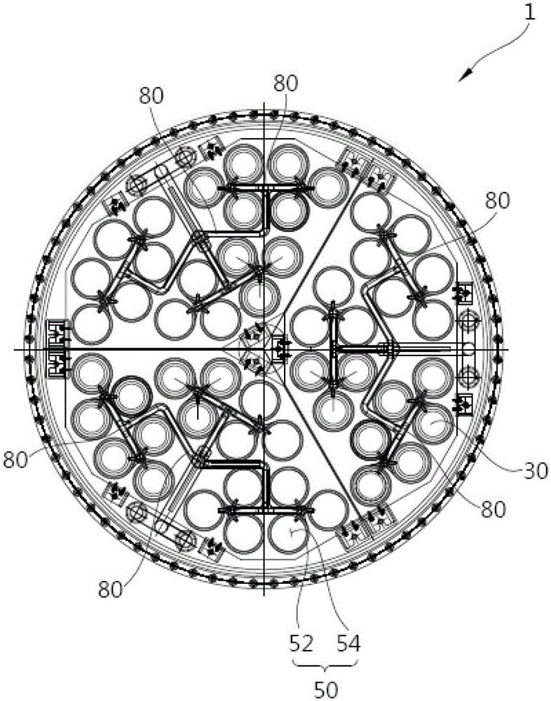
[0069] figure 1 is a cross-sectional view of a polysilicon deposition apparatus according to an embodiment of the present invention, figure 2 It is a plan view of the polysilicon deposition apparatus according to the embodiment of the present invention.

[0070] like figure 1 and figure 2 As shown, the polysilicon deposition apparatus 1 according to the first embodiment of the present invention includes a reaction chamber 20 , a silicon core rod 30 and a jacket unit 50 .

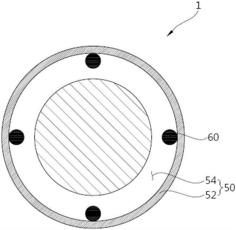
[0071] The reaction chamber 20 is used for accommodating the silicon core rod 30 and the jacket unit 50 . The number N of silicon core rods 30 is arranged inside the reaction chamber 20 and has a pair of silicon rods 32 that are energized by current. The polysilicon is deposited by the reaction of the process gas while being heated by the energized current. Moreover, the jacket unit 50 is formed with M receiving holes 54 for receiving N silicon core rods 30 having a pair of silicon rods 32, and the rea...

no. 2 example

[0094] Figure 5 is a perspective view of a polysilicon deposition apparatus according to a second embodiment of the present invention, Image 6 Yes Figure 5 A top view of the polysilicon deposition apparatus shown, and, Figure 7 It is a perspective view of a partial region of a jacket unit of a polysilicon deposition apparatus according to a second embodiment of the present invention combined with a shielding member.

[0095] Before explaining, it should be noted that Figure 7 The jacketed unit shown is shown in the Figure 5 and Figure 5 Partial area of ​​the jacketed unit shown, and described below Figure 8 to Figure 10 Partial area of ​​jacketed unit shown.

[0096] like Figure 5 to Figure 7 As shown, the polysilicon deposition apparatus 1 according to the second embodiment of the present invention includes a silicon core rod 130 , a jacket unit 150 and a shielding member 220 .

[0097] There are a plurality of silicon core rods 130 , and polysilicon is depos...


PUM


Abstract

The invention relates to a polycrystalline silicon deposition device comprising a reaction chamber, silicon core rods with the number of N and a jacket unit. The silicon core rods are disposed in the reaction chamber, each comprise a pair of silicon rods energized through current, are heated by the current and deposit polycrystalline silicon through the reaction of process gas; the jacket unit comprises receiving holes with the number of M; the receiving holes receive the silicon core rods each comprising a pair of silicon rodS; the process gas is supplied to the receiving holes for reaction; and the jacket unit cools the pairs of the silicon rods of the silicon core rods of the receiving holes with the number of M.

Description

technical field [0001] The present invention relates to a polysilicon deposition device, more specifically, a polysilicon deposition device for depositing polysilicon on the surface of a silicon core rod by supplying a process gas to a working space containing a silicon core rod. Background technique [0002] Polycrystalline silicon, called polysilicon, is widely used as a material in cutting-edge industries such as the semiconductor and solar industries. The polysilicon used in such cutting-edge industries as the semiconductor and solar industries is produced by reduction reaction of quartz or sand with carbon to produce metallic silicon, and then undergoes a further refining process to be used as a single crystal material for semiconductor wafer manufacturing or a solar cell substrate. materials used. [0003] Polysilicon production methods are mainly divided into Siemens method (Siemens), fluidized bed (Fluidizedbed) method and vapor-liquid deposition method (VLD: Vapor-...

Claims


Application Information

Patent Timeline
Patent Type & Authority Patents(China)
IPC IPC(8): C01B33/035
Inventor 朴钟薰金昇铉李旭基李昶徕姜承吾朴奎东张今相
Owner SEMIMATERIALS
Learn More