
Solar energy heat pump combined sludge drying system and drying method

A solar heat pump and sludge drying technology, which is applied in dehydration/drying/concentrated sludge treatment, energy wastewater treatment, etc., can solve problems such as inoperability, heat pump performance degradation, evaporator tube wall and air heat transfer coefficient are small, etc. , to achieve the effect of reducing primary energy consumption and carbon emission intensity

Active Publication Date: 2014-01-01
TECHNICAL INST OF PHYSICS & CHEMISTRY - CHINESE ACAD OF SCI
View PDF4 Cites 21 Cited by
  • Summary
  • Abstract
  • Description
  • Claims
  • Application Information

AI Technical Summary

Problems solved by technology

[0004] However, the solar energy system in the existing sludge drying equipment combined with solar energy and heat pump has only heat collecting equipment, but no heat storage equipment
In this way, the heat load absorbed by solar energy in summer may be greater than the heat load required by the drying equipment, resulting in low energy utilization in summer
[0005] Secondly, the heat pump drying system in the existing sludge drying equipment combined with solar energy and heat pump uses an air source heat pump, but due to the cold winter in northern my country, if the outdoor ambient temperature drops below 0°C, if the air source heat pump is still used for heating , the performance of the heat pump will be significantly reduced or even unable to work. In addition, due to the small heat transfer coefficient between the evaporator tube wall and the air, the sludge drying equipment that uses air source heat pump combined with solar energy and heat pump occupies an area of larger

Method used


Image

  • Solar energy heat pump combined sludge drying system and drying method
  • Solar energy heat pump combined sludge drying system and drying method
  • Solar energy heat pump combined sludge drying system and drying method

Examples


Embodiment Construction

[0028] The specific implementation manners of the present invention will be further described in detail below in conjunction with the accompanying drawings and embodiments. The following examples are used to illustrate the present invention, but are not intended to limit the scope of the present invention.

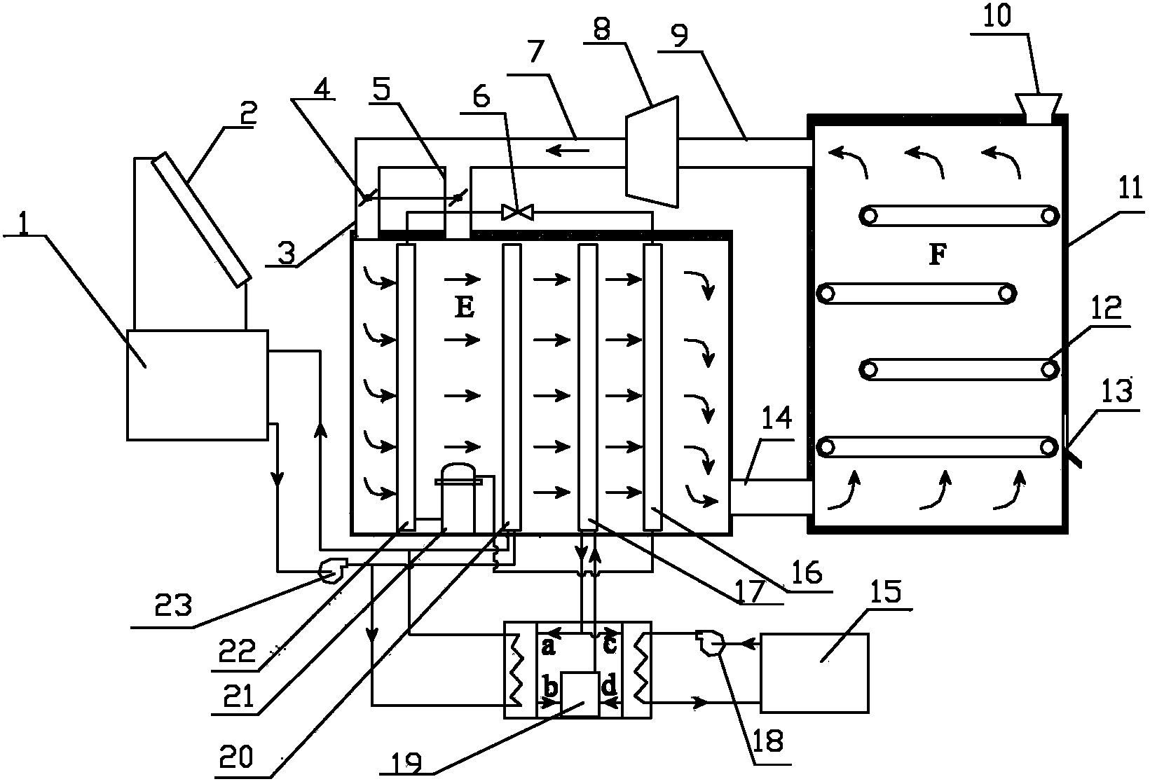
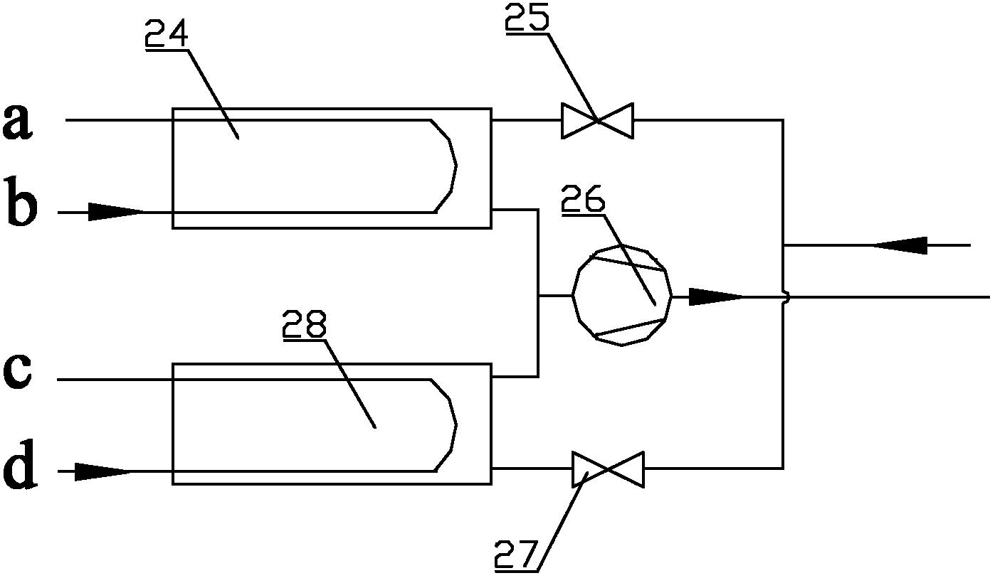
[0029] Such as figure 1 As shown, a solar heat pump combined with sludge drying system according to the present invention includes a solar heating subsystem, a heat pump subsystem and a drying device subsystem, and the heat pump subsystem includes an air source heat pump subsystem and a reclaimed water source heat pump subsystem. The solar heating subsystem includes a heat collector 2 for collecting solar radiation energy, a hot water storage tank 1, a first water pump 23 and a hot water coil 20; the hot water storage tank 1 and the first The water pump 23 and the hot water coil 20 are connected through pipelines to form a closed water circulation system. The water in t...


PUM


Abstract

The present invention discloses a solar energy heat pump combined sludge drying system, which comprises a solar energy heat supply subsystem, a heat pump subsystem and a drying device subsystem, wherein the heat pump subsystem comprises an air source heat pump subsystem and a reclaimed water source heat pump subsystem, the solar energy heat supply subsystem comprises a heat collection device for collecting solar radiation energy, a hot water storage tank, a first water pump and a hot water coil pipe, and the hot water storage tank, the first water pump and the hot water coil pipe are connected through pipelines to form a sealed water circulation system. According to the present invention, solar energy heat can be effectively utilized, water vapor latent heat in wet air can be recovered, and energy required by sludge drying at night or in case of insufficient solar energy can be ensured with the solar energy heat supply subsystem and the reclaimed water source heat pump subsystem.

Description

technical field [0001] The invention relates to the technical field of sludge drying, in particular to a solar heat pump combined sludge drying system and drying method. Background technique [0002] According to the "Decision of the State Council on Implementing the Scientific Outlook on Development and Strengthening Environmental Protection", by 2010, the urban sewage treatment rate will not be lower than 70%. At the end of the "Eleventh Five-Year Plan", the national urban sewage treatment capacity will reach 1.0×10 8 m 3 / d, the annual sewage treatment capacity reaches 3.0×10 10 m 3 , the sludge output will reach 3.0×10 7 t (80% moisture content). With the increase of sewage treatment rate and treatment depth, sludge discharge is increasing at a rate of more than 10-15% per year. Sludge treatment and disposal has become an environmental bottleneck for urban development. The resource utilization of sludge has become an important means of sludge treatment and disposa...

Claims


Application Information

Patent Timeline
IPC IPC(8): C02F11/12
CPCY02W10/37
Inventor 张振涛杨鲁伟吕君戴群特
Owner TECHNICAL INST OF PHYSICS & CHEMISTRY - CHINESE ACAD OF SCI
Learn More