
Construction method for blocking depressurization well by adopting accelerated cement

A technology of quick-setting cement and construction method, which is applied in the fields of filling, earthwork drilling, sealing/packing, etc., can solve the problems of the influence of the construction progress of the foundation pit floor, the complex well sealing process, and the long plugging period, etc. The effect of wasting materials, simple operation procedures, and shortened construction period

Inactive Publication Date: 2014-01-01
SHANGHAI NO 7 CONSTR
View PDF7 Cites 3 Cited by
  • Summary
  • Abstract
  • Description
  • Claims
  • Application Information

AI Technical Summary

Problems solved by technology

[0005] (2) For the normal water output of the decompression well in the later stage of the pit greater than 6m 3 In the case of / h, special well sealing measures are considered, generally in the form of filling melon seeds in the well pipe and then grouting, but the sealing process is more complicated, there are more plugging procedures and the plugging period is longer, for the whole The construction progress of the foundation pit floor has a certain influence

Method used


Image

  • Construction method for blocking depressurization well by adopting accelerated cement
  • Construction method for blocking depressurization well by adopting accelerated cement
  • Construction method for blocking depressurization well by adopting accelerated cement

Examples


Embodiment Construction

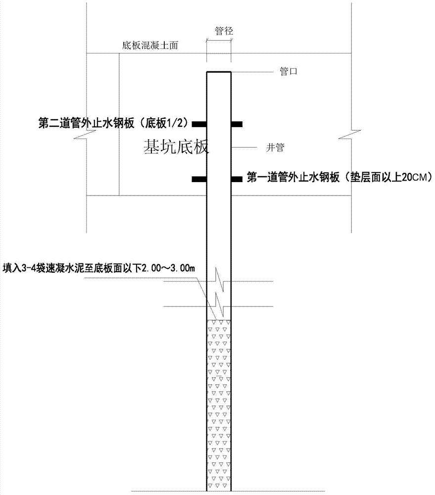
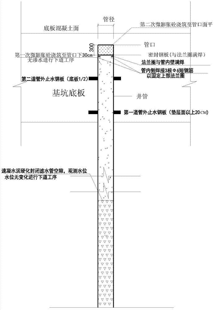
[0034] The specific embodiments of the present invention are given below in conjunction with the drawings, but the present invention is not limited to the following embodiments. According to the following description and claims, the advantages and features of the present invention will be clearer. It should be noted that the drawings all adopt a very simplified form and all use imprecise ratios, which are only used for the purpose of conveniently and clearly assisting in describing the embodiments of the present invention.

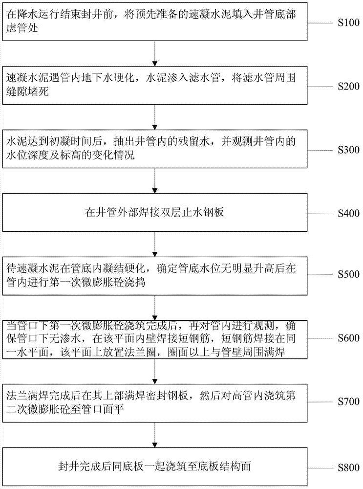
[0035] Please refer to figure 1 , figure 1 Shown is a flow chart of a construction method for plugging a pressure-reducing well with quick-setting cement according to a preferred embodiment of the present invention. The present invention proposes a construction method for plugging a pressure-reducing well with quick-setting cement, which includes the following steps:

[0036] Step S100: Fill the pre-prepared quick-setting cement into the filter tube at the bot...


PUM

PropertyMeasurementUnit
lengthaaaaaaaaaa
diameteraaaaaaaaaa
thicknessaaaaaaaaaa

Abstract

The invention discloses a construction method for blocking a depressurization well by adopting accelerated cement. The construction method includes the step 1, filling a filter pipe on the bottom of a well casing with the accelerated cement after precipitation and before well blocking, step 2, blocking gaps around the filter pipe after the cement hardens when meeting underground water in the casing and after the cement seeps into the filter pipe, step 3, pumping residual water in the well casing out after the cement reaches initial setting time, step 4, welding two layers of water stop steel plates outside the well casing, step 5, carrying out primary microdilatancy concrete pouring and smashing in the casing when the water level on the bottom of the casing does not rise obviously after the cement sets and hardens in the bottom of the casing, step 6, guaranteeing that water seepage does not exist below a casing mouth, welding short steel bars in the plane, placing a flange ring, and carrying out full weld on the portion, above the ring face and the portion, around a casing wall, step 7, welding and sealing the steel plates fully on the upper portion of the flange after full-weld is carried out on the flange, and then carrying out secondary microdilatancy concrete pouring in a high casing until the casing mouth face is flat, and step 8, pouring the high casing and a bottom plate to a bottom plate structural face after well blocking is completed. According to the construction method, operation is quick and convenient, well blocking periods are short, cost is low, and the construction method can be applied to later-stage different water yield situations of the depressurization well in a pit.

Description

Technical field [0001] The invention relates to the field of construction, and in particular to a construction method for plugging a pressure-reducing well by using quick-setting cement to improve the water-stop effect after the pressure-reducing well is blocked. Background technique [0002] With the rapid development of modern construction industry, large-scale buildings are equipped with deeper and larger basements. The use of underground space in deep foundation pits has become a trend in modern buildings. With the continuous excavation of foundation pits, the phenomenon of groundwater surges There are certain hidden safety hazards to the construction of deep foundation pits, and at the same time, the dewatering effect of deep foundation pits is required to be higher and higher. In the construction, in order to speed up the progress of the project, the dewatering construction generally needs to reach the designed dewatering depth within a few weeks before the excavation of th...

Claims


Application Information

Patent Timeline
Patent Type & Authority Applications(China)
IPC IPC(8): E02D17/18E21B33/13
Inventor 张希陆林辉龚斌王骁骏吴杏弟季方
Owner SHANGHAI NO 7 CONSTR
Learn More